41-8
Software Configuration Guide—Release IOS XE 3.6.0E and IOS 15.2(2)E
OL_28731-01
Chapter 41 Configuring VRF-lite
Configuring VRF-lite for IPv4
The following example shows how to configure multicast within a VRF table:
Switch(config)# ip routing
Switch(config)# ip vrf multiVrfA
Switch(config-vrf)# ip multicast-routing vrf multiVrfA
Switch(config-vrf)# interface GigabitEthernet3/1/0
Switch(config-if)# ip vrf forwarding multiVrfA
Switch(config-if)# ip address 172.21.200.203 255.255.255.0
Switch(config-if)# ip pim sparse-mode
For more information about configuring a multicast within a Multi-VRF CE, see the
Cisco IOS IP Multicast Configuration Guide, Release 12.4.
Use the no ip vrf vrf-name global configuration command to delete a VRF and to remove all interfaces
from it. Use the no ip vrf forwarding interface configuration command to remove an interface from the
VRF.
Configuring a VPN Routing Session
Routing within the VPN can be configured with any supported routing protocol (RIP, OSPF, or BGP) or
with static routing. The configuration shown here is for OSPF, but the process is the same for other
protocols.
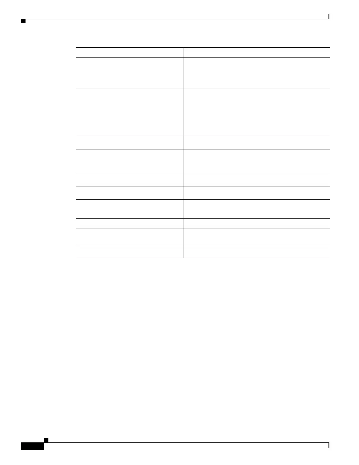
Step 5
Switch(config-vrf)# rd
route-distinguisher
Creates a VRF table by specifying a route distinguisher.
Enter either an AS number and an arbitrary number
(xxx:y) or an IP address and arbitrary number
(A.B.C.D:y).
Step 6
Switch(config-vrf)# route-target
{export | import | both}
route-target-ext-community
Creates a list of import, export, or import and export route
target communities for the specified VRF. Enter either an
AS system number and an arbitrary number (xxx:y) or an
IP address and an arbitrary number (A.B.C.D:y).
The route-target-ext-community value should be the same
as the route-distinguisher value entered in Step 4.
Step 7
Switch(config-vrf)# import map
route-map
(Optional) Associates a route map with the VRF.
Step 8
Switch(config-vrf)# interface
interface-id
Enters interface configuration mode and specifies the
Layer 3 interface to be associated with the VRF. The
interface can be a routed port or a SVI.
Step 9
Switch(config-if)# ip vrf forwarding
vrf-name
Associates the VRF with the Layer 3 interface.
Step 10
Switch(config-if)# ip address
ip-address mask
Configures IP address for the Layer 3 interface.
Step 11
Switch(config-if)# ip pim
[sparse-dense mode | dense-mode |
sparse-mode]
Enables PIM on the VRF-associated Layer 3 interface.
Step 12
Switch(config-if)# end
Returns to privileged EXEC mode.
Step 13
Switch# show ip vrf [brief | detail |
interfaces
] [vrf-name]
Verifies the configuration. Display information about the
configured VRFs.
Step 14
Switch# copy running-config
startup-config
(Optional) Saves your entries in the configuration file.
Command Purpose

 Loading...


