22-5
Software Configuration Guide—Release IOS XE 3.5.0SG and IOS 15.2(2)SG
OL-27597-01
Chapter 22 Configuring STP and MST
About STP
Creating the STP Topology
The goal of the spanning tree algorithm is to make the most direct link the root port. When the spanning
tree topology is calculated based on default parameters, the path between source and destination end
stations in a switched network might not be optimal according to link speed. For instance, connecting
higher-speed links to a port that has a higher number than the current root port can cause a root-port
change.
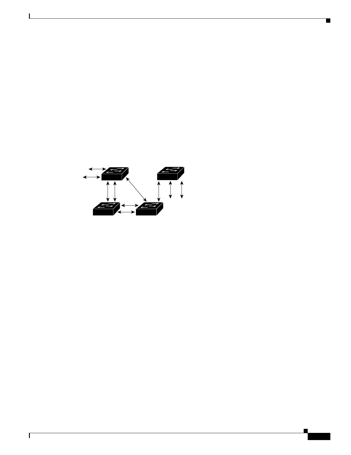
In Figure 22-1, Switch A is elected as the root bridge. (This could happen if the bridge priority of all the
switches is set to the default value [32,768] and Switch A has the lowest MAC address.) However, due
to traffic patterns, the number of forwarding ports, or link types, Switch A might not be the ideal root
bridge. By increasing the STP port priority (lowering the numerical value) of the ideal switch so that it
becomes the root bridge, you force a spanning tree recalculation to form a new spanning tree topology
with the ideal switch as the root.
Figure 22-1 Spanning Tree Topology
For example, assume that one port on Switch B is a fiber-optic link, and another port on Switch B (an
unshielded twisted-pair [UTP] link) is the root port. Network traffic might be more efficient over the
high-speed fiber-optic link. By changing the spanning tree port priority on the fiber-optic port to a higher
priority (lower numerical value) than the priority set for the root port, the fiber-optic port becomes the
new root port.
STP Port States
Propagation delays can occur when protocol information passes through a switched LAN. As a result,
topology changes can take place at different times and at different places in a switched network. When
a Layer 2 interface transitions directly from nonparticipation in the spanning tree topology to the
forwarding state, it can create temporary data loops. Ports must wait for new topology information to
propagate through the switched LAN before starting to forward frames. They must allow the frame
lifetime to expire for frames that have been forwarded under the old topology.
Each Layer 2 interface on a switch that uses spanning tree exists in one of the following five states:
• Blocking—In this state, the Layer 2 interface does not participate in frame forwarding.
• Listening—This state is the first transitional state after the blocking state when spanning tree
determines that the Layer 2 interface should participate in frame forwarding.
• Learning—In this state, the Layer 2 interface prepares to participate in frame forwarding.
• Forwarding—In this state, the Layer 2 interface forwards frames.
S5688
DP
DP
RP DP
DP
RP
DP
RP = Root Port
DP = Designated Port
DP
RP
DP
DA
CB

 Loading...


