42-3
Software Configuration Guide—Release IOS XE 3.6.0E and IOS 15.2(2)E
OL_28731-01
Chapter 42 Configuring Quality of Service
Overview of QoS
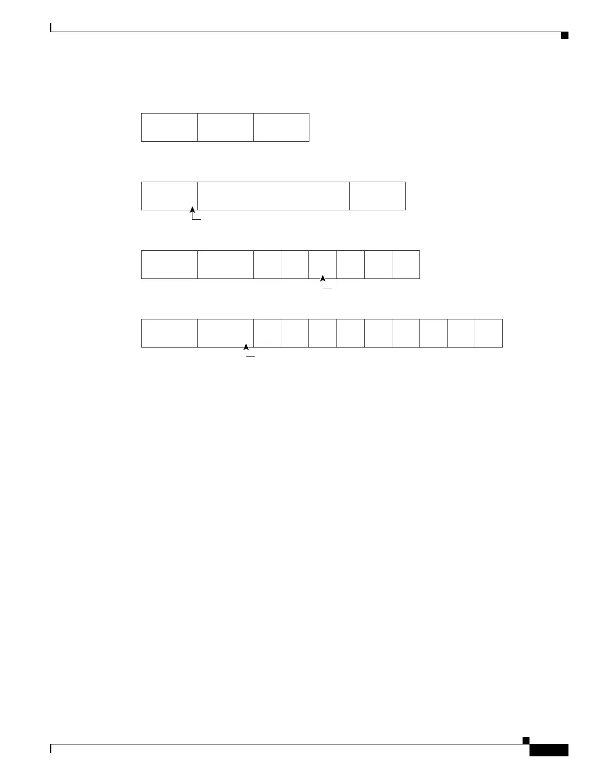
Figure 42-1 QoS Classification Layers in Frames and Packets
All switches and routers across the Internet rely on the class information to provide the same forwarding
treatment to packets with the same class information and different treatment to packets with different
class information. The class information in the packet can be assigned by end hosts or by switches or
routers along the way, based on a configured policy, detailed examination of the packet, or both. Detailed
examination of the packet is expected to happen closer to the edge of the network so that the core
switches and routers are not overloaded.
Switches and routers along the path can use the class information to limit the amount of resources
allocated per traffic class. The behavior of an individual device when handling traffic in the DiffServ
architecture is called per-hop behavior. If all devices along a path provide a consistent per-hop behavior,
you can construct an end-to-end QoS solution.
Implementing QoS in your network can be a simple or complex task and depends on the QoS features
offered by your internetworking devices, the traffic types and patterns in your network, and the
granularity of control you need over incoming and outgoing traffic.
QoS Terminology
The following terms are used when discussing QoS features:
• Packets carry traffic at Layer 3.
• Frames carry traffic at Layer 2. Layer 2 frames carry Layer 3 packets.
• Labels are prioritization values carried in Layer 3 packets and Layer 2 frames:
–
Layer 2 class of service (CoS) values, which range between zero for low priority and seven for
high priority:
Layer 2 Inter-Switch Link (ISL) frame headers have a 1-byte User field that carries an IEEE
802.1p CoS value in the three least significant bits.
68140
Encapsulated Packet
Layer 2
header
IP header
3 bits used for CoS
Data
Layer 2 ISL Frame
ISL header
(26 bytes)
Encapsulated frame ...
FCS
(4 bytes)
Layer 2 802.1Q/P Frame
Preamble
Start frame
delimiter
DA
Len
SA Ta g PT Data FCS
Layer 3 IPv4 Packet
Version
length
To S
(1 byte)
ID Offset TTL Proto FCS IP-SA IP-DA Data
3 bits used for CoS (user priority)
IP precedence or DSCP

 Loading...


