41-23
Software Configuration Guide—Release IOS XE 3.6.0E and IOS 15.2(2)E
OL_28731-01
Chapter 41 Configuring VRF-lite
Configuring VRF-lite for IPv6
Configure VRFs
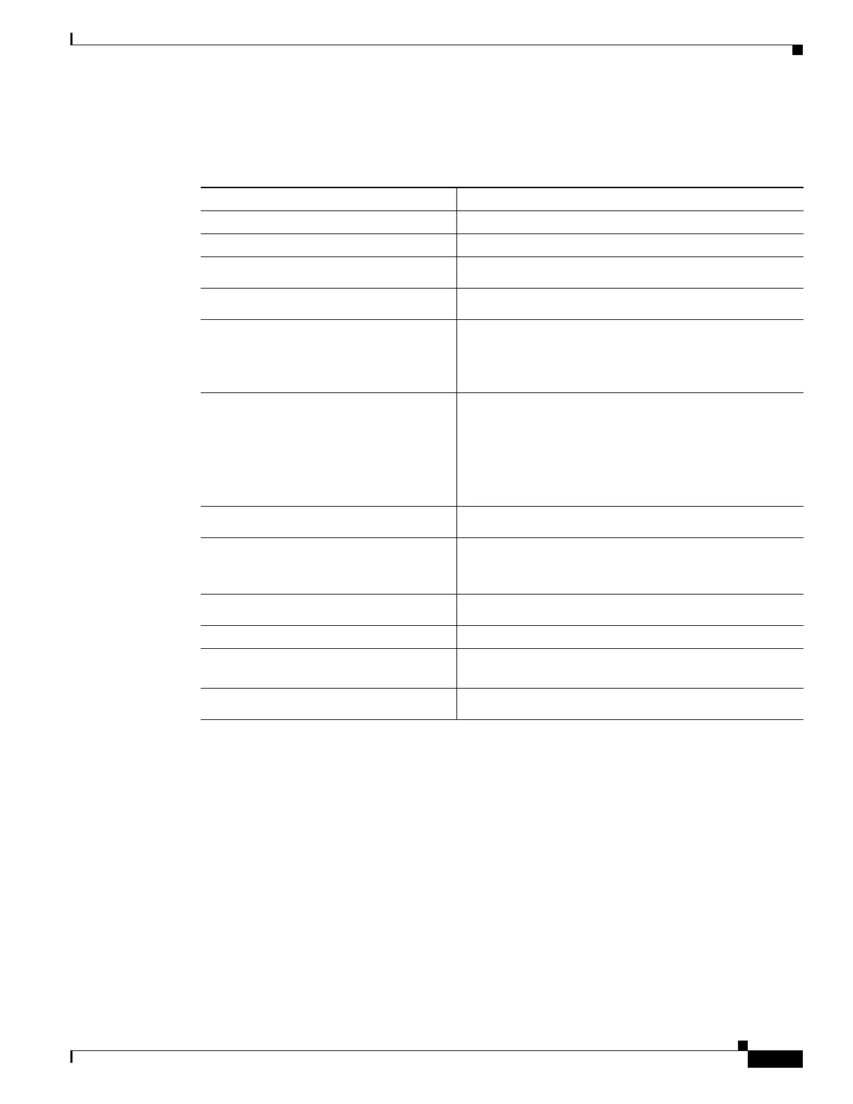
To configure one or more VRFs, perform this task:
This example shows how to configure VRFs:
Switch(config)# vrf definition red
Switch(config-vrf)# rd 100:1
Switch(config-vrf)# address family ipv6
Switch(config-vrf-af)# route-target both 200:1
Switch(config-vrf)# exit-address-family
Switch(config-vrf)# interface Ethernet0/1
Switch(config-if)# vrf forwarding red
Switch(config-if)# ipv6 address 5000::72B/64
Command Purpose
Step 1
Switch# configure terminal
Enters global configuration mode.
Step 2
Switch(config)# ipv6 routing
Enables IPv6 routing.
Step 3
Switch(config)# vrf definition
vrf-name
Names the VRF and enters VRF configuration mode.
Step 4
Switch(config-vrf)# address-family
ipv4 | ipv6
(Optional) IPv4 by default. Configuration MUST for ipv6.
Step 5
Switch(config-vrf)# rd
route-distinguisher
(Optional) Creates a VRF table by specifying a route
distinguisher. Enter either an Autonomous System number
and an arbitrary number (xxx:y) or an IP address and
arbitrary number (A.B.C.D:y).
Step 6
Switch(config-vrf)# route-target
{export | import | both}
route-target-ext-community
(Optional) Creates a list of import, export, or import and
export route target communities for the specified VRF.
Enter either an AS system number and an arbitrary number
(xxx:y) or an IP address and an arbitrary number
(A.B.C.D:y).
Note This command is effective only if BGP is running.
Step 7
Switch(config-vrf)# import map
route-map
(Optional) Associates a route map with the VRF.
Step 8
Switch(config-vrf)# interface
interface-id
Enters interface configuration mode and specify the Layer
3 interface to be associated with the VRF. The interface
can be a routed port or SVI.
Step 9
Switch(config-if)# ip vrf forwarding
vrf-name
Associates the VRF with the Layer 3 interface.
Step 10
Switch(config-if)# end
Returns to privileged EXEC mode.
Step 11
Switch# show ip vrf [brief | detail
| interfaces] [vrf-name]
Verifies the configuration. Displays information about the
configured VRFs.
Step 12
Switch# copy running-config
startup-config
(Optional) Saves your entries in the configuration file.

 Loading...


