41-7
Software Configuration Guide—Release IOS XE 3.6.0E and IOS 15.2(2)E
OL_28731-01
Chapter 41 Configuring VRF-lite
Configuring VRF-lite for IPv4
The following example lists all the steps to configure per-VRF TACACS+:
Switch> enable
Switch# configure terminal
Switch (config)# ip vrf cisco
Switch (config-vrf)# rd 100:1
Switch (config-vrf)# exit
Switch (config)# interface Loopback0
Switch (config-if)# ip vrf forwarding cisco
Switch (config-if)# ip address 10.0.0.2 255.0.0.0
Switch (config-if)# exit
Switch (config-sg-tacacs+)# ip vrf forwarding cisco
Switch (config-sg-tacacs+)# ip tacacs source-interface Loopback0
Switch (config-sg-tacacs)# exit
For more information about configuring per-VRF for TACACS+ server,
http://www.cisco.com/en/US/docs/ios/sec_user_services/configuration/guide/sec_vrf_tacas_svrs.pdf
Configuring Multicast VRFs
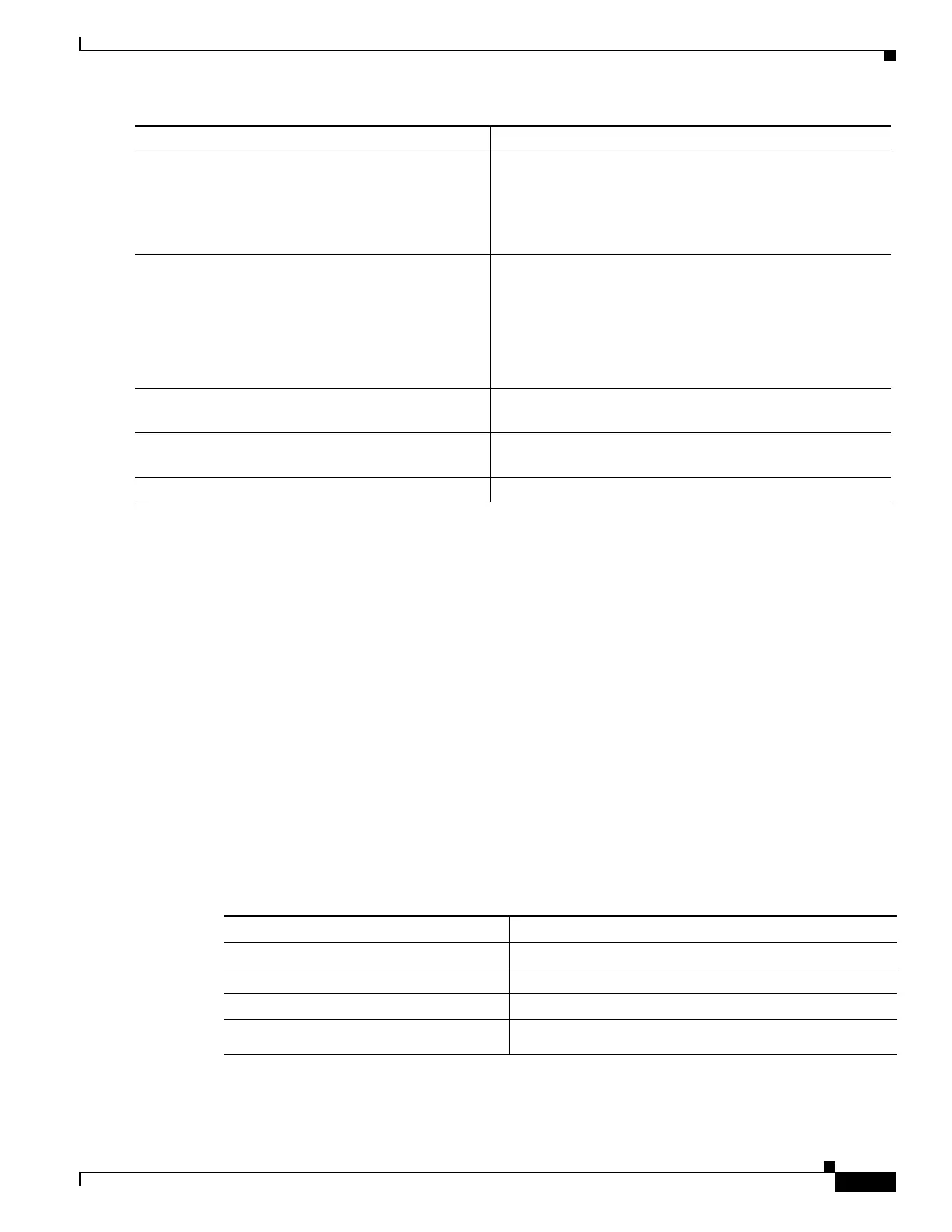
To configure multicast within a VRF table, perform this task:
Step 10
aaa group server tacacs+ group-name
Example:
Switch (config)# aaa group server tacacs+
tacacs1
Groups different TACACS+ server hosts into distinct lists
and distinct methods and enters server-group configuration
mode.
Step 11
server-private {ip-address | name} [nat]
[single-connection] [port port-number]
[timeout seconds] [key [0 | 7] string]
Example:
Switch (config-sg-tacacs+)# server-private
10.1.1.1 port 19 key cisco
Configures the IP address of the private TACACS+ server
for the group server.
Step 12
Switch (config-sg-tacacs+)# ip vrf forwarding
vrf-name
Configures the VRF reference of a AAA TACACS+ server
group.
Step 13
Switch (config-sg-tacacs+)# ip tacacs
source-interface subinterface-name
Uses the IP address of a specified interface for all outgoing
TACACS+ packets.
Step 14
Switch (config-sg-tacacs)# exit
Exits server-group configuration mode.
Command or Action Purpose
Command Purpose
Step 1
Switch# configure terminal
Enters global configuration mode.
Step 2
Switch(config)# ip routing
Enables IP routing.
Step 3
Switch(config)# ip vrf vrf-name
Names the VRF and enters VRF configuration mode.
Step 4
Switch(config-vrf)# ip
multicast-routing vrf vrf-name
(Optional) Enables global multicast routing for VRF table.

 Loading...


