27-25
Software Configuration Guide—Release IOS XE 3 6.0E and IOS 15.2(2)E
OL_28731-01
Chapter 27 Configuring IGMP Snooping and Filtering, and MVR
Configuring MVR
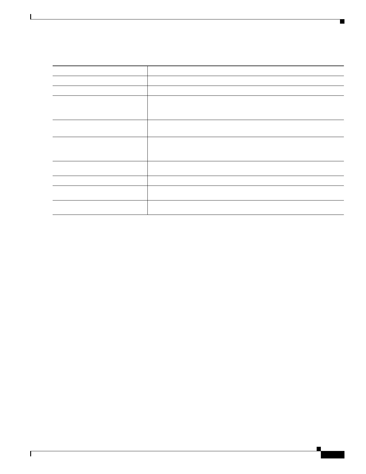
To configure MVR parameters, perform these steps:
To return a switch to the default settings, use the no mvr [mode | group ip-address | querytime | vlan]
global configuration commands.
The following example shows how to enable and verify MVR:
Switch(config)# mvr
Switch(config)# mvr vlan 100
Switch(config)# mvr group 225.1.1.1
Switch(config)# mvr querytime 10
Switch(config)# mvr mode dynamic
Switch(config)# end
Switch# show mvr
MVR Running: TRUE
MVR multicast VLAN: 100
MVR Max Multicast Groups: 500
MVR Current multicast groups: 1
MVR Global query response time: 10 (tenths of sec)
MVR Mode: dynamic
Switch# show mac address-table
Multicast Entries
vlan mac address type ports
---------+---------------+-------+--------------------------------------------
100 0100.5e01.0101 igmp Fa2/1
Switch# show platform hardware mac-address-table address 0100.5e01.0101
Flags are:
----------
D - Drop
ND - Do not drop
Index Mac Address Vlan Type SinglePort/RetIndex/AdjIndex
----- -------------- ----- ---------- ---------------------------------
40048 0100.5E01.0101 100 Ret 104444
Switch# show platform hardware ret chain index 104444
RetIndex 104444
Command Purpose
Step 1
Switch# configure terminal
Enters global configuration mode.
Step 2
Switch(config)# mvr
Enables MVR on the switch.
Step 3
Switch(config)# mvr group
ip-address [count]
Configures an IP multicast address on the switch or uses the count parameter
to configure a contiguous series of MVR group addresses (maximum of 500
groups).
Step 4
Switch(config)# mvr querytime
value
(optional) Defines the maximum wait time for IGMP report memberships on
a receiver port before removing the port from multicast group membership.
Step 5
Switch(config)# mvr vlan
vlan-id
Specifies the VLAN in which multicast data is received; all source ports must
belong to this VLAN. The VLAN ID range is 1 to 1001 and 1006 to 4094. The
default is VLAN 1.
Step 6
Switch(config)# mvr mode
{dynamic | compatible}
Specifies the MVR mode of operation.
Step 7
Switch(config)# end
Returns to privileged EXEC mode.
Step 8
Switch# show mvr or show mvr
members
Verifies the configuration.
Step 9
Switch# copy running-config
startup-config
(Optional) Saves your entries in the configuration file.

 Loading...


