CDM-570A/570AL Satellite Modem with Optional Packet Processor
Revision 5
Rear Panel Connectors and Pinouts 3–7 MN-CDM570A
3.2.2 Terrestrial Data Connections Group
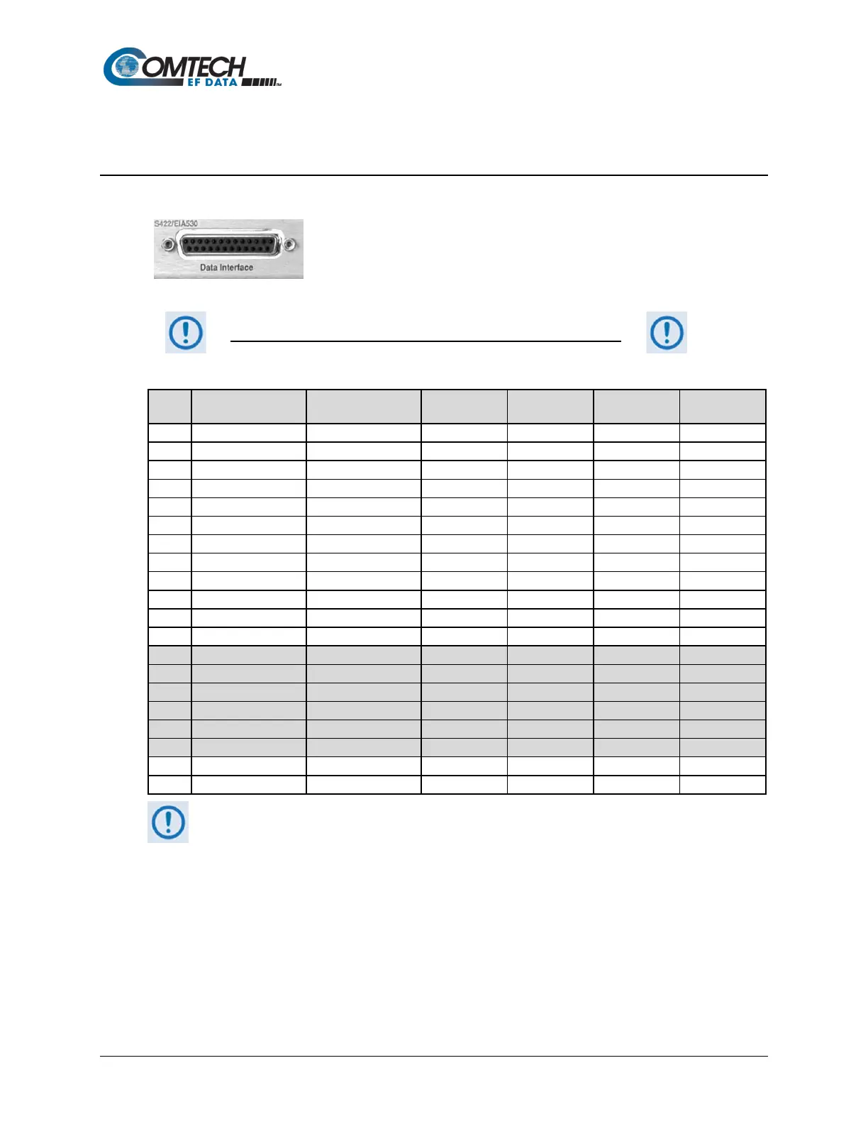
3.2.2.1 Data Interface Connector, DB-25F
This 25-pin ‘D’ type female (DB-25F) Data Interface connector conducts
data input and output breakout panel switching protection. This
connector conforms to the EIA-530 pinout, which allows for connection
of different electrical standards, including EIA-422, V.35, and EIA-232.
Shielded connectors resolve EMC problems unlike sometimes-used V.35 Winchester connectors.
THE MODEM IS ALWAYS ASSUMED TO BE DCE
Table 3-2. Data Interface Connector Pin Assignments
Pin #
Generic Signal
Description
Direction
V.35 EIA-232 Circuit #
1. This table is ordered by “Generic Signal Description” and not by connector pin orientation.
2. When the rear-panel switch marked “1:N Switch” is in the OFF position, all of the signals shown above
are available and functional. In addition, pins not shown are not connected, and therefore no damage
will occur if other signals are connected to the additional pins.
3. When the rear-panel switch marked “1:N Switch” is in the ON position, the highlighted signals, plus pins
18, 20, 21, 22, 23 and 25 are reserved for use by the 1:N system. DO NOT connect signals to any of
these pins in this mode. Certain pins have DC voltages present that may damage equipment other than
a Comtech EF Data redundancy switch.
4. For X.21 operation, use the EIA-422 pins, but ignore Receive Clock if the Modem is DTE, and ignore
Transmit Clocks if the Modem is DCE.