CDM-570A/570AL Satellite Modem with Optional Packet Processor
Revision 5
Rear Panel Connectors and Pinouts 3–20 MN-CDM570A
Do these steps (Figure 3-10):
WARNING! ENSURE THAT THE POWER IS REMOVED FROM THE DC CIRCUIT
BEFORE PROCEEDING!
1. Plug the user-supplied, male keyed DC power lead connector into the mating female
connector until the lock tab engages. Number 18 AWG minimum wires are
recommended.
2. Connect the user-supplied DC power leads to the power source.
3. Energize the DC power source to turn the modem ON.
3.3.3.2.2 Optional DC Operation – Replace the DC Power Fuses
For optional DC operation, the modem requires two different fuses that are contained within the
press-fit fuse holder.
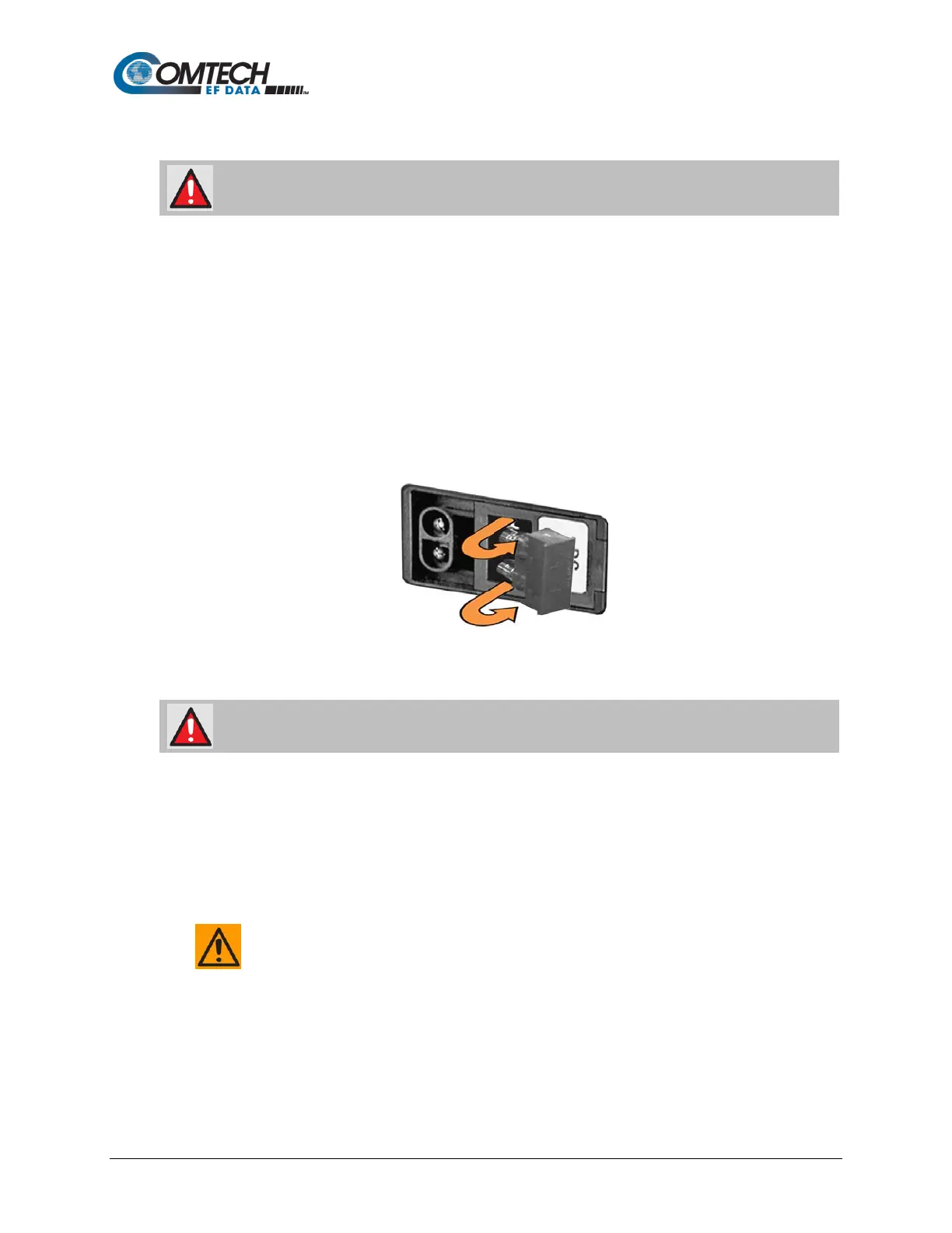
Figure 3-11. Replace the Optional DC Chassis Fuses
Do these steps (Figure 3-11):
WARNING! DISCONNECT THE POWER SUPPLY BEFORE PROCEEDING!
1. Unseat the fuse holder from the IEC power module:
• Pry the holder outward from the module.
• Pull the holder straight out, and then swing the holder away from the module.
2. Remove and replace the 20mm Slo-Blo fuses as needed.
CAUTION – FOR CONTINUED OPERATOR SAFETY, ALWAYS REPLACE THE
FUSES WITH THE CORRECT TYPE AND RATING.
• Use T3.15A fuses for units without a BUC
• Use T8A fuses for units with a BUC.
3. Reseat the fuse holder in the IEC power module.