4 Layout
1
2
3
4
5
6 7
8
9
10
11
12
13
14
1516
17
18
15
19
20
21
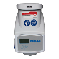
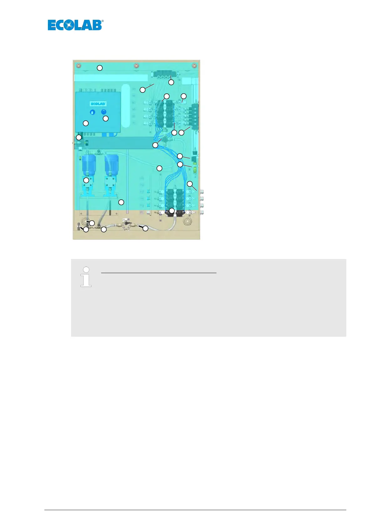
Fig. 4: Layout of ULTRAX Compact
1 Wall bracket
2 Terminal box
3 Filter pressure regulator
4 Diaphragm pumps
5 Wall attachment / Spacer
6 Overflow floater switch
7 Sump
8 Oval gear meter
9 Diaphragm valve manifold block. Product side.
10 Pull relief for suction pipe connections
11 Bracket for the measuring vessel
12 Mud guard
13 Flow rate sensor
14 Sampling tap
15 Rinsing valve blocks
16 Pilot valve connections
17 Metering line connections
18 Diaphragm valve manifold block. Machine side
19 Flush lines
20 Pilot valves
21 Splash guard curtain
The following items are not shown:
– Suction lines (not included in scope of the equipment)
– Suction pipes (not included in scope of the equipment)
– Product supply container (not included in scope of the equipment)
– Compressed air connection
– Water connection
– Extension unit on product side, machine side, rinsing valves (optional)
Layout
39 MAN046590 Rev. 6-03.2022