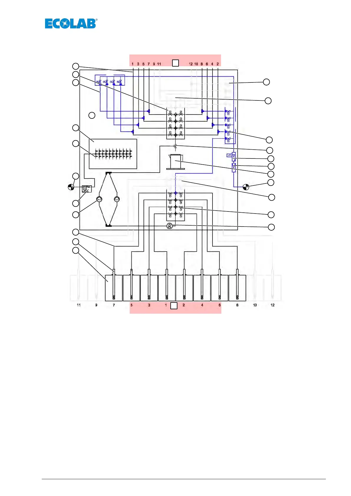
5.3 Process diagram
A
B
1
2
3
4
8
9
11
12
13
14
15
17
18
19
20
21
22
23
24
25
26
27
28
Fig. 5: Process diagram
A Washer extractor
B Product
1 Wall bracket
2 Terminal box
3 Filter pressure regulator
4 Diaphragm pumps
8 Oval gear meter
9 Diaphragm valve manifold block. Product side.
11 Bracket for the measuring vessel
12 Mud guard
13 Flow rate sensor
14 Sampling tap
15 Rinsing valve blocks
17 Metering line connections
18 Diaphragm valve manifold block Machine side
19 Flush lines
20 Pilot valve
22 Suction pipes (not included in scope of the equipment)
23 Product container
24 Compressed air connection
25 Water connection
26 * Expansion unit on the product side
27 * Expansion unit on the machine side
28 * Expansion unit on the rinsing valves
- * Expansion pipes (9, 10, 11, 12) are shown light.
Function description
43 MAN046590 Rev. 6-03.2022