5.4 Function components
Illustration Description
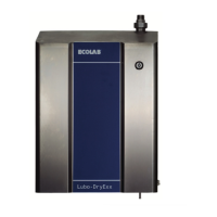
Water inlet valve
Ä
Chapter 4 ‘Layout’ on page 39 , Fig. 4 , no. 12 & 13.
Consisting of:
n Dirt filter,
Fig. 4 , no. 12.
n Flow sensor, Fig. 4 , no. 13.
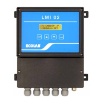
Flow sensor
Monitoring the water flow rate in flushing processes.
Ä
Chapter 4 ‘Layout’ on page 39 , Fig. 4 , No. 13.
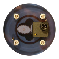
Rinsing valve blocks
Flushing the diaphragm valve manifold blocks and the metering pipes into the washer
extractors.
Ä
Chapter 4 ‘Layout’ on page 39 , Fig. 4 , no. 15.
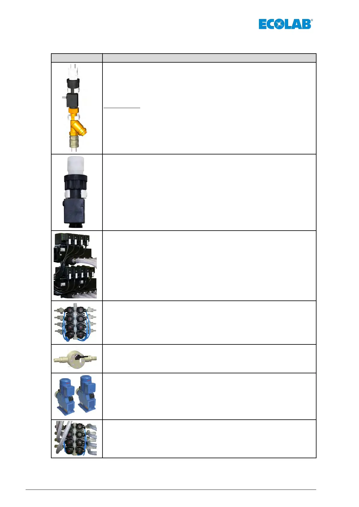
Diaphragm valve manifold block – product side
Input manifold for up to 8 different washing products.
Ä
Chapter 4 ‘Layout’ on page 39 , Fig. 4 , No. 9.
Oval gear meter
Monitoring the flow rate of each of the washing products.
Ä
Chapter 4 ‘Layout’ on page 39 , Fig. 4 , No. 8
and
Ä
Chapter 1.1.1 ‘Further instructions’ on page 6 .
Diaphragm pumps (2 x)
Metering the washing products from the supply containers into the relevant washer
extractors.
Ä
Chapter 4 ‘Layout’ on page 39 , Fig. 4 , No. 4
and
Ä
Chapter 1.1.1 ‘Further instructions’ on page 6 .
Diaphragm valve manifold block – machine side
Output manifold for up to 8 dif
ferent washer extractors.
Ä
Chapter 4 ‘Layout’ on page 39 , Fig. 4 , No. 18.
Function description
44MAN046590 Rev. 6-03.2022