Note: Use unshielded cable of maximum 20 m length to connect IO-Link devices.
Connecting IO-Link device for class A port
Figure 163: Connection IO-Link device for class A port (DI Connection optional)
Note: The use of the additional digital input at the DI connection is optional. It can be use
as digital input, e.g. if the IO-Link device provides an additional switching signal.
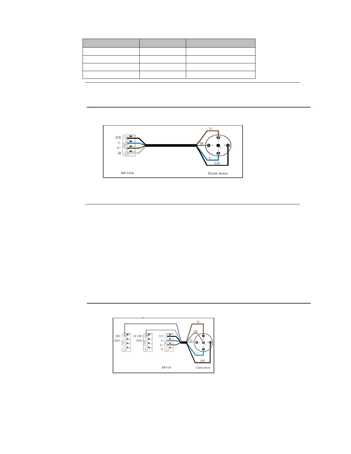
Connecting IO-Link device for class B port
To connect an IO-Link device with class B port to your RSTi-EP station, you also need the
following potential distribution modules:
1. For input Current Path
− EP-711F
− EP-710F
2. For output current Path
− EP-751F
− EP-700F
Figure 164: Connecting IO-Link Device for Class B
a. Install the three modules in a RSTi-EP station.
b. Connect the IO-Link device as shown in the above figure.

 Loading...


