User Manual Section 4
GFK-2958L May 2021
Detailed Descriptions of the Fieldbus Network Adapters 78
Figure 29: EP-3264 3-wire Connection Diagram
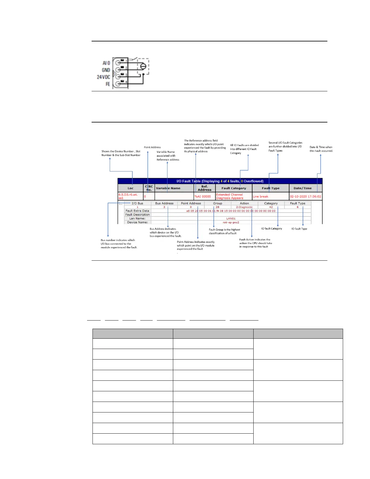
Now if sensor supply “AI 0” signal is disconnected from the connector of the EP-3264,an
“Extended Channel Specific Diagnostics, Diagnosis Appears” will be recorded in IO Fault
Table as “Fault Category” & “Line Break" will be recorded as “Fault Type”.
Figure 30: IO Fault table Description- Extended Channel Specific Diagnostics
As shown in figure, 21 bytes of Fault Extra Data is provided in IO Fault table as a part of
Extended Channel Diagnostic Data.
The data displayed for Alarm Specifier, Channel Properties, Channel Error type, Extended
Channel error type, Extended Channel Address vaule, Extra Data & Maintenance Status are
based on Standard PROFINET protocol specifications.
In this example, the decoding of the Fault Extra Data is as follows:
a8 05 28 05 00 06 01 f4 08 15 00 00 00 00 00 00 00 00 00 00 00

 Loading...


