EPSON EPL-N4000/EPL-N4000+ Chapter 2 Operating Principles
Rev.B 65
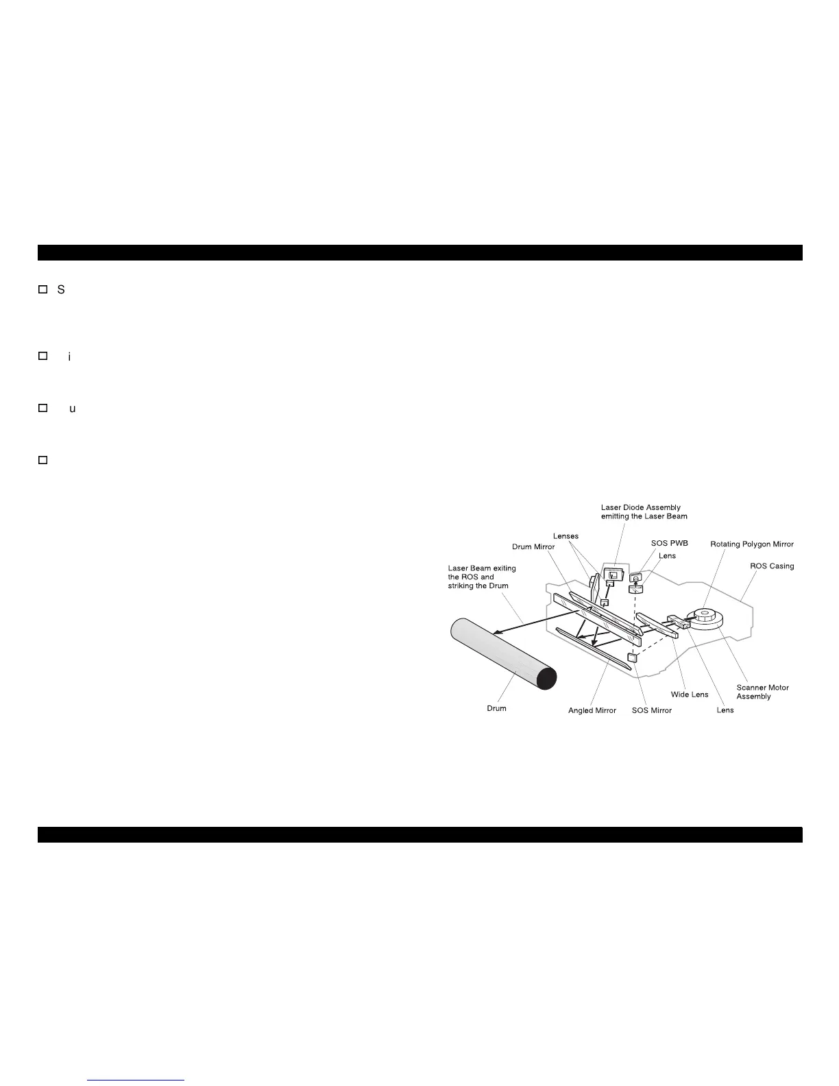
Scanner Motor Assembly
The Scanner Motor Assembly is attached to the Scanner Motor
Assembly PWB. The +24VDC Motor rotates at a constant speed.
The Scanner Motor Assembly is electrically connected to the MCU.
Wide Lens
A lens that focuses the beam comin
on Mirror and
directs it onto the An
led Mirror.
Drum Mirror
An
led so it reflects the laser beam comin
led Mirror,
down onto the surface of the drum.
SOS PWB (Start Of Scan Sensor)
The SOS Sensor is in-line with the laser beam sweep. The laser
beam strikes the SOS Sensor at the be
of each sweep to let
the printer control circuity know that a new scan has started. The
SOS PWB is electrically connected to the MCU PWB.
2.3.2 ROS Operation
The MCU PWB supplies +5VDC to drive the Laser Diode
semiconductor. The semiconductor uses the +5VDC to
enerate a 5
milliwatt beam of invisible laser li
ht. As is characteristic of
semiconductor devices, the Laser Diode can switch states very rapidly.
A switchin
circuit on the Laser Diode PWB switches the Laser Diode
on and off accordin
e data sent from the C262 main board. Two
lenses, an an
led mirror, and another two lenses focus the laser beam
onto the rotatin
on Mirror has twelve
mirrored sides and rotates at approximately 15,000 RPM. The Poly
on
Mirror reflects the laser beam back throu
h the two lenses and onto the
An
led Mirror. The movement of the Poly
on Mirror reflects the laser
beam in a sweepin
motion, from side to side, across the An
led Mirror;
with one complete sweep for each mirrored side. The An
led Mirror
reflects the laser beam onto the Drum Mirror.
The Drum Mirror is ali
le so the mirror reflects the
sweepin
beam down onto the surface of the Drum. The combination of
the rapid sweepin
of the laser beam across the surface of the char
ed
Drum and the rapid switchin
on and off of the laser beam creates, on
the Drum, an invisible electrical ima
e that corresponds to the screen
ima
e that was sent from the host computer. Located at one corner of
the ROS, near the end of the An
led Mirror is the Start of Scan Sensor
(SOS) Mirror. The Start of Scan Sensor is located at the opposite corner
of the ROS Assembly. Each sweep of the laser beam be
the SOS Mirror, reflectin
the beam into the SOS Lens, which focuses
the beam onto the SOS Sensor. The SOS Sensor is electrically
connected to the MCU PWB. When the laser beam strikes the Sensor,
the Sensor notifies the MCU that a new scan has started.
Figure 2-20. Structure of ROS
sr1323x