EPSON EPL-N4000/EPL-N4000+ Chapter 2 Operating Principles
Rev.B 76
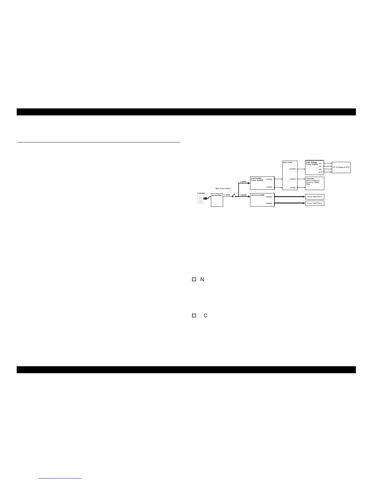
2.6 Operating Principles for Power Supply
Circuit
2.6.1 Power Supply Circuit
The power supplies in this printer provide the volta
es that the printer
requires to operate. The various printer functions require 110VAC,
+5VDC, +24VDC, and several hi
e DC and AC values that are
used by xero
raphics.
The printer AC power cord plu
rounded AC wall outlet. The
cord carries AC line volta
e to the
Noise Filter PWB
. The Noise Filter
smooths the AC volta
e and sends it to the Main Power Switch.
Switchin
on the Main Power Switch applies AC volta
e to the AC
Driver PWB and to the Low Volta
e Power Supply (LVPS) PWB.
The
AC Driver PWB
is the interface between printer control (MCU) and
the Fuser. Fuser sensors connected to the AC Driver PWB send Fuser
status information to the Driver PWB, which the PWB routes to the MCU
PWB. The MCU processes the information and sends commands back
to the AC Driver PWB to tell the AC Driver whether or not to switch on
the Fuser Heat Rods.
The
Low Voltage Power Supply PWB
, or LVPS, converts the 110VAC
to re
ulated +24VDC and +5VDC volta
es. The LVPS sends these
volta
es to the MCU PWB. The MCU uses the volta
es for internal
processin
and for printer component operation. The MCU also sends
+24VDC to the Hi
e Power Supply PWB.
The
High Voltage Power Supply PWB
, or HVPS, converts the
+24VDC received from the MCU PWB to the hi
es that are
required by the xero
raphic system of the printer. The HVPS produces
the Char
e (CR), Transfer (TR), Developer Bias (DB), and Detack
(DTS) volta
es, and sends them on to the EP Cartrid
e and to the Bias
Transfer Roll (BTR).
Figure 2-36. Power Supply Circuit
2.6.2 Power Supply Components
This printer is made up of five main components and a number of
subcomponents.
Noise Filter PWB
Smooths and removes any fluctuation or hum from the AC line
volta
e.
Main Power Switch:
Used to switch AC volta
e on and off
(switches the printer on and off).
AC Driver PWB
Receives smoothed AC volta
e from the Noise Filter. The AC Driver
PWB receives Fuser temperature information from Fuser sensors
and passes that information on to the MCU for processin
. The
MCU PWB commands the AC Driver to switch on or switch off AC
volta
e to the Fuser Heat Rods.
sr1301xa