Maintenance 3. Covers
N6 Rev.2 125
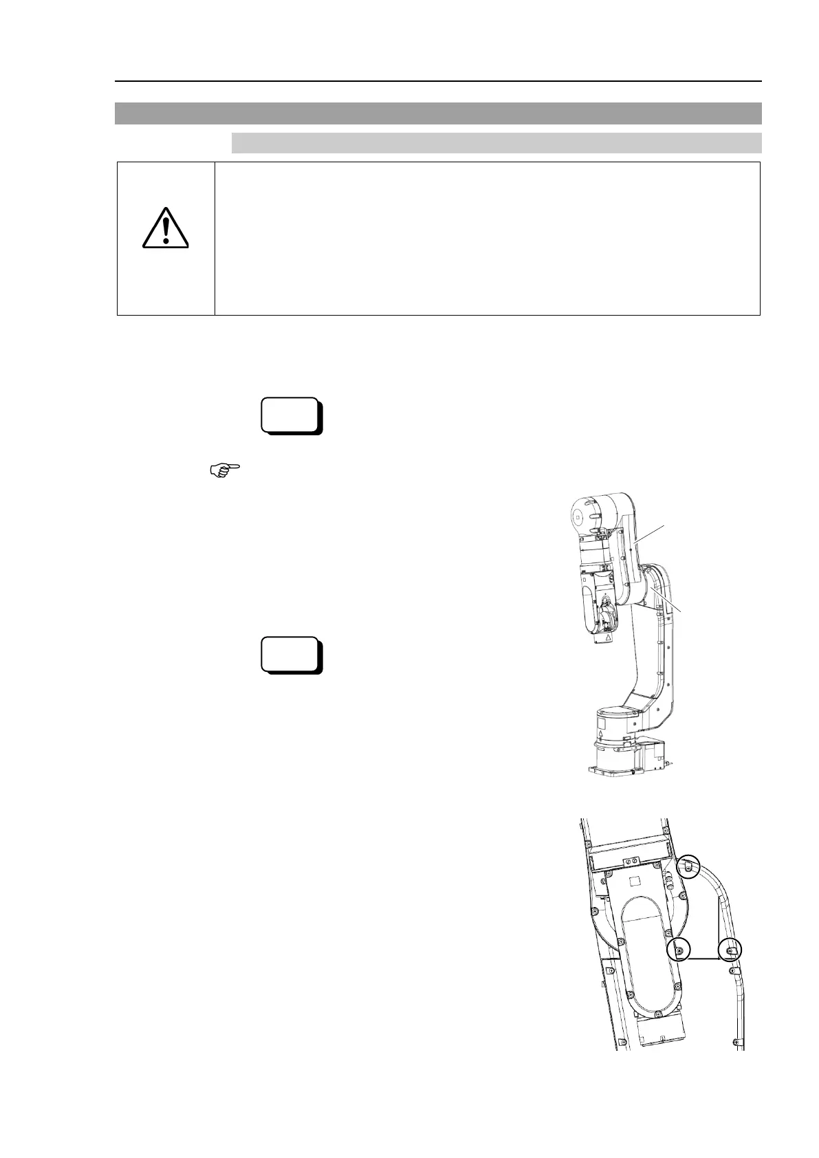
3.6 Joint #2 Cover
3.6.1 N6-A1000** (Joint #2 Cover)
CAUTION
■
When installing the cover, b
e careful not to get the cables caught in it or bend
m forcibly to push into the cover.
Unnecessary strain on cables may result in damage to the cables, disconnection,
and/or contact failure. These are extremely
hazardous and may result in electric
shock and/or improper function of the robot system.
routing the cables, check the cable locations at removing the cover. Be
place the cables back to their original locations.
controller.
Release the Joint #2 brake.
> brake off, 2
When releasing the brake, be careful of the arm falling due to its own weight.
the Arm #2 about 100 degrees to a position
where you can remove the screws of the Joint #
2
Operate the brake of the J
oint #2.
> brake on, 2
the controller.
screws, and then remove the Joint #2
Cross recessed binding head machine screw:
3-M4×8

 Loading...


