Maintenance 5. Actuator Units
N6 Rev.2 277
5.1.4 Joint #1 (N6-A850*BR): Cable direction: Upward
Removal
Joint #1
Actuator Unit
N6-A850*BR
Cable direction:
Upward
the covers.
Base cover, Joint #1 cover, and Joint #1 inside cover
For details, refer to Maintenance 3. Covers.
Remove the J1 cable fixing plate fixed on the Arm #1.
For details, refer to the Removal step (49) in Maintenance 4.3 Cable Unit
(N6-A850*R): Cable direction Standard (backward).
Remove the cable unit inside the base.
For details, refer to the Removal steps (2), (4) through (7), and (9) through (15)
in Maintenance 4.4 Cable Unit (N6-A850*BR): Cable direction Upward.
cable unit inside the Joint #1.
For details, refer to the Removal steps (56) through (58), and (60) in
Maintenance 4.3 Cable Unit (N6-A850*R): Cable direction Standard
(backward).
Disconnect the M/C cable.
For details, refer to Maintenance 4.6. M/C Cable.
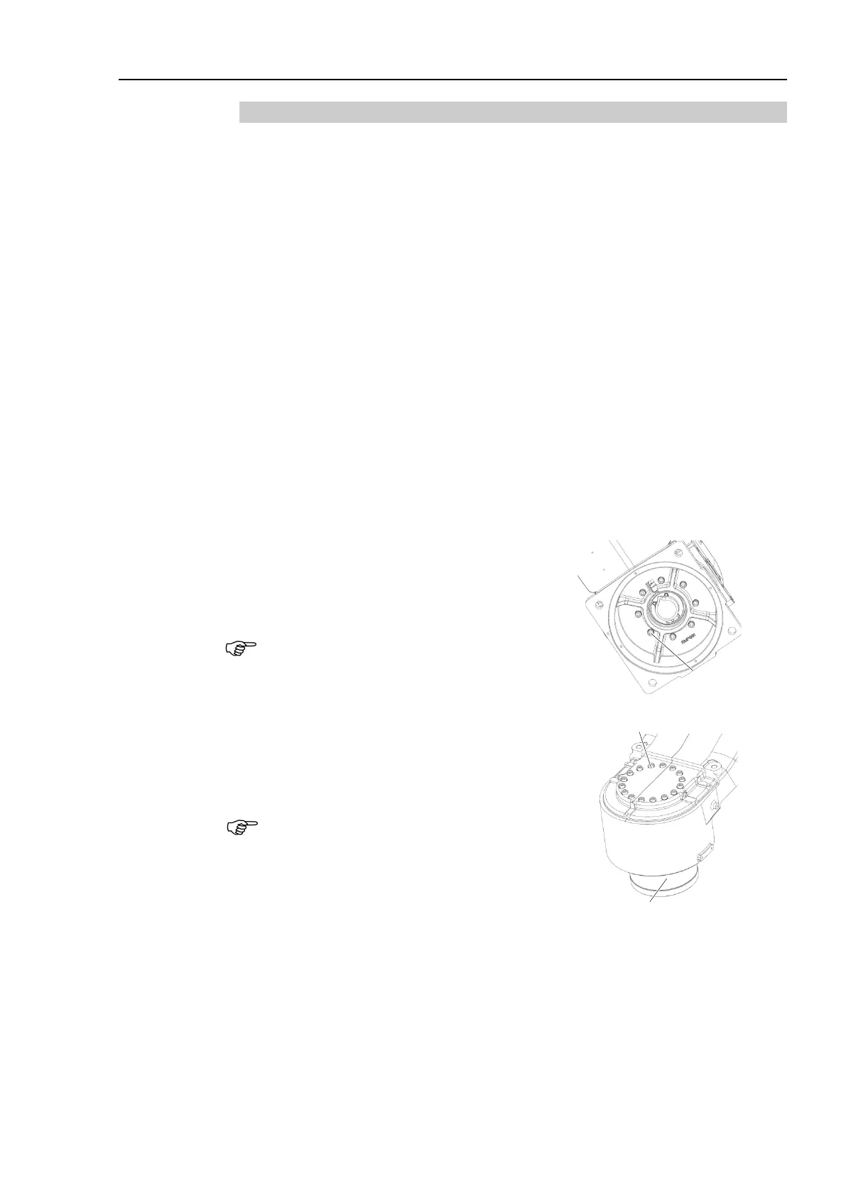
Remove the base.
Hexagon socket head cap bolts:
8-M6×40 (with plain washer)
When you remove it, be careful not to catch
the cables on the Joint #1 actuator unit.
8-M6×
40
(with plain washer)
Remove the Joint #1 actuator unit and the
O-ring.
Hexagon socket head cap bolts:
16-M5×35 (with plain washer)
Be sure to have at least 2 people to perform
the operation since the parts being heavy.
Do not apply excessive shock to the parts.
16-M5×35 (with plain washer)

 Loading...


