Maintenance 3. Covers
132 N6 Rev.2
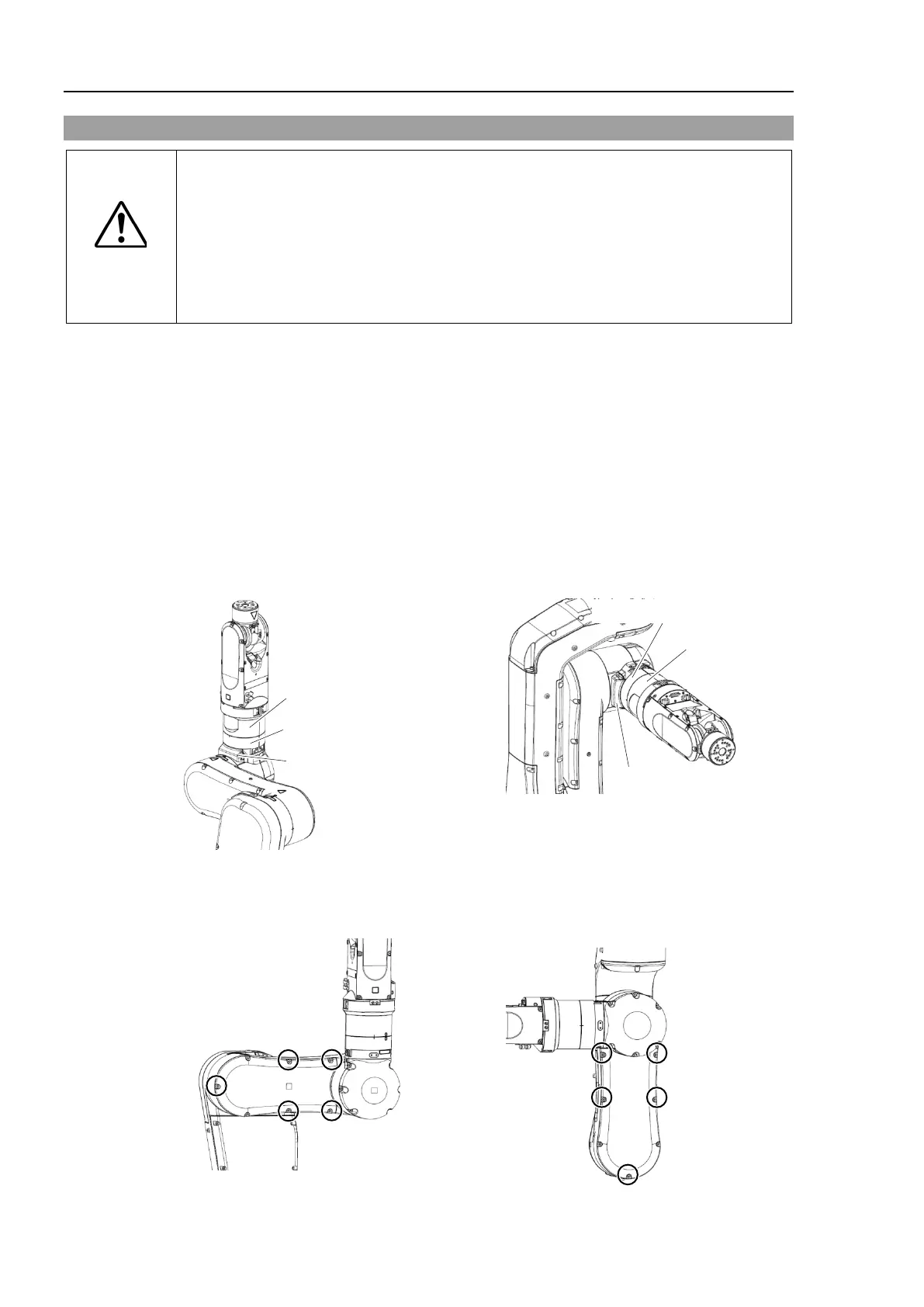
3.8 Arm #2 Cover (Arm #3 side)
CAUTION
■
When installing the cover, b
e careful not to get the cables caught in it or bend
m forcibly to push into the cover.
Unnecessary strain on cables may result in damage to the cables, disconnection,
and/or contact failure. These are extremely hazardous and may result in electric
shock and/or improper function of the robot system.
routing the cables, check the cable locations at removing the cover. Be
place the cables back to their original locations.
Remove the following covers in order.
Joint #4 inside cover
Joint #4 side cover (Arm #2 side)
Arm #3 inside cover
Details are described in the following sections:
Maintenance
3.9 Arm #3 Inside Cover
3.12 Joint #4 Inside Cover
3.11 Joint #4 Side Cover
below of the screws that fix the Arm #2 cover (Arm #3 side).
Cross recessed binding head machine screw: 5-M4×8

 Loading...


