Maintenance 5. Actuator Units
N6 Rev.2 307
5.5.3 Replacing the Joint #5 Electromagnetic Brake
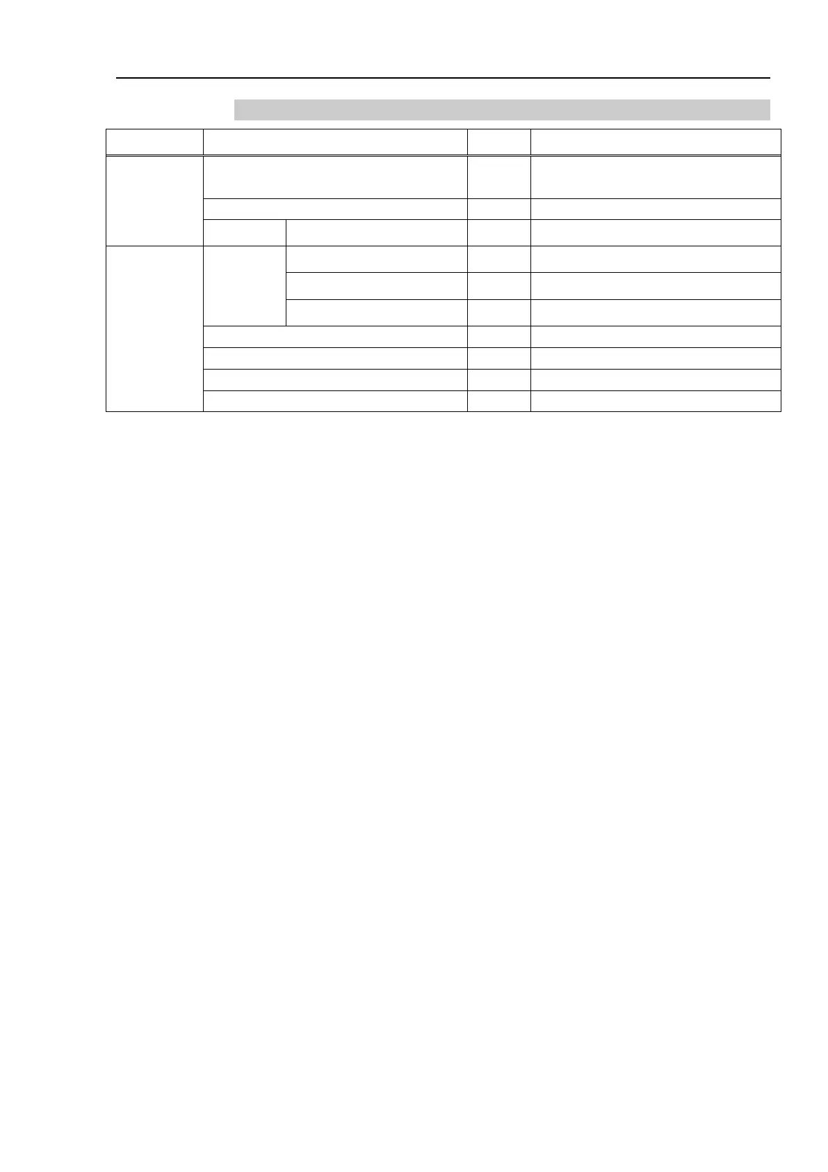
Name Qty Code, Note
Maintenance
Parts
Electromagnetic Brake 1
1670649
(Common to Joint #5 and #6)
Cable tie AB200 - 1684328 1 bag (100 ties: white)
Tools
Hexagonal
wrench
width across flats: 2 mm 1 For M4 hexagon socket set screw
width across flats: 2.5 mm 1 For M3 hexagon socket head cap bolts
width across flats: 3 mm 1 For M4 hexagon socket head cap bolts
Cross-point screwdriver (#2)
For cross recessed head screws
For tightening torque control
For positioning of drive boss
* The belt tensile jig is an assembly jig. Use this jig when adjusting belt tension.
The brake is mounted on each joint to prevent the arm from lowering due to its own
weight while the controller power is OFF or the motor is OFF status. The brake does not
work during replacement. Be careful when performing maintenance work.
Removal
(1)
Remove the Joint #5 electromagnetic brake.
For details, refer to Removal steps (1) through (10) in Maintenance
Replacing the Joint #5 Motor Unit.
Installation
(1)
Install the Joint #5 electromagnetic brake.
For details, refer to Installation steps (2) through (10) in Maintenance
Replacing the Joint #5 Motor Unit.

 Loading...


