Maintenance 5. Actuator Units
290 N6 Rev.2
5.3.2 Joint #3 (N6-A850**R)
Removal
Joint #3
Actuator Unit
N6-A850**R
Arm #4 side cover (2 covers), Joint #4 inside cover, Joint #4 outside cover
Joint #4 side cover (2 covers), Arm #3 cover, Arm #3 inside cover
Arm #2 cover (2 covers), Arm #1 inside cover
For details, refer to Maintenance 3. Covers.
Remove the cable unit from Joint #1 to Joint #3.
For details, refer to the Removal steps (3) through (6), (9) through (25), (27),
(29), (33) in Maintenance 4.3 Cable Unit (N6-A850*R): Cable direction
Standard (backward).
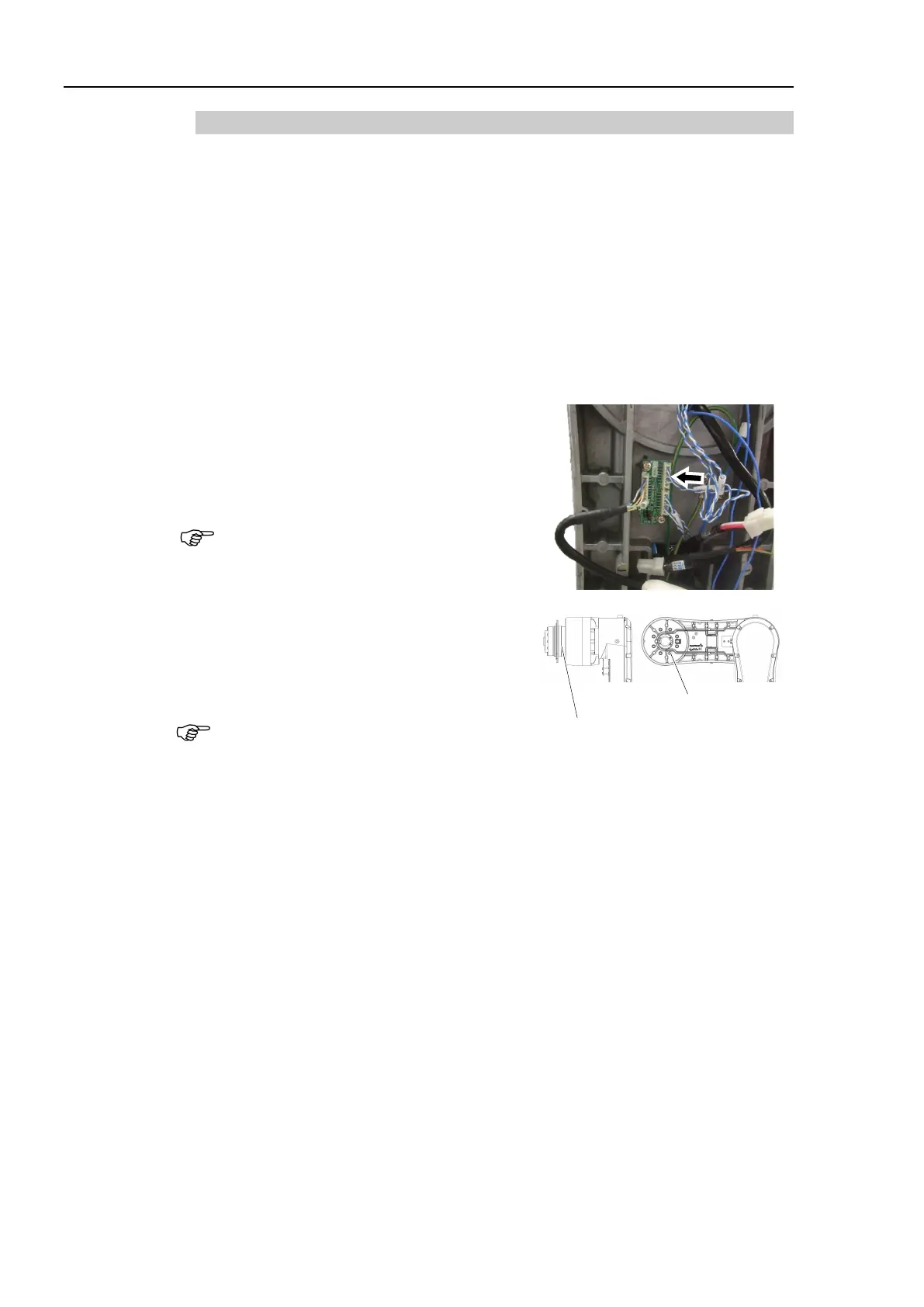
Disconnect the connector connected to the
encoder board 2.
Connector:
EB0x_CN2 (Joint #3 side)
Be careful that the jumper pins on the board
do not come off.
4) Remove the Joint #3 actuator unit and the
O-ring.
Hexagon socket head cap bolts:
8-M6×35 (with plain washer)
Be sure to have at least 2 people to perform
the operation since the parts being heavy.
When you remove it, be careful not to catch
the cables on the Joint #3 actuator unit.
8-M6×35 (with plain washer)

 Loading...


