Setup & Operation 3. Environment and Installation
N6 Rev.2 37
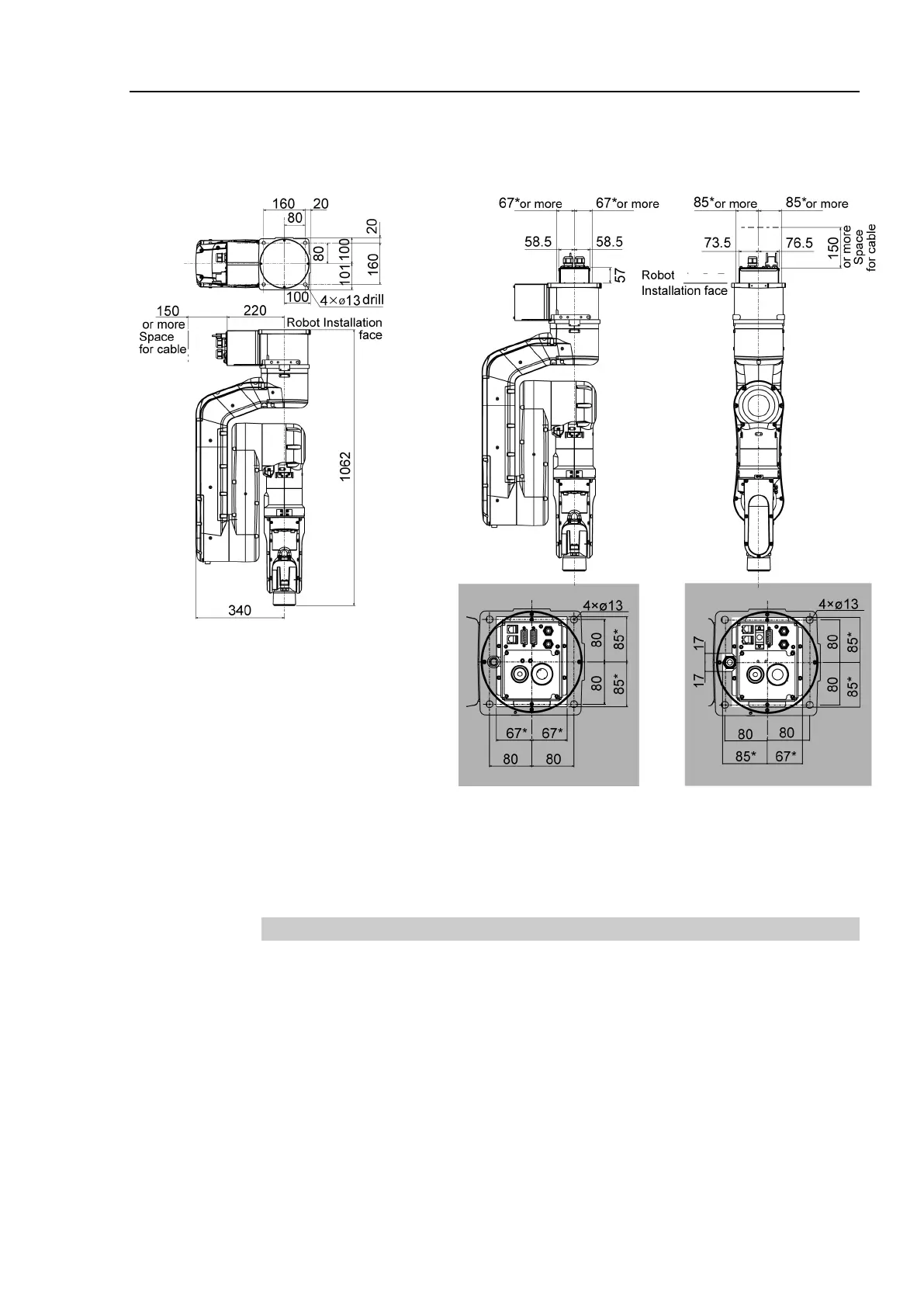
N6-A850**R:
Cable direction: Standard (backward)
Cable direction: Upward
*: Example of space for Manipulator base for “Cable
direction: Upward”:
Design the base table as shown above considering not
interfering with the positioning holes and the installation
holes.
3.3.3 Motion range
The following figures are the cases when the length of the end effector is 100 mm.
Match the ranges with the actual end effector length. If the camera or the
electromagnetic valve attached on the Arm is large, define the max motion ranges by
considering the area where these tools may reach.
When operating in narrow space with the basic orientation, make sure to consider the
radius of the arm rotation as shown the figure below. The Manipulator must be installed
to avoid interference with peripherals during operation.

 Loading...


