Maintenance 3. Covers
130 N6 Rev.2
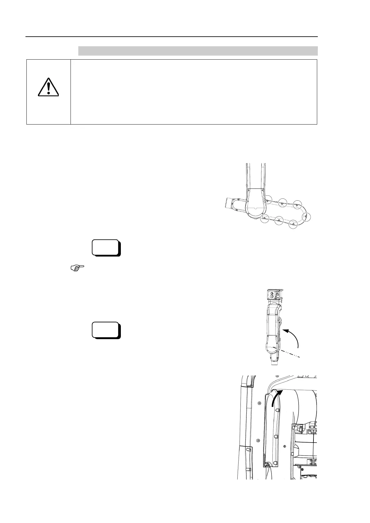
3.7.2 N6- A850**R (Arm #2 Cover, Arm #1 Side)
CAUTION
■
When installing the cover, b
e careful not to get the cables caught in it or
m forcibly to push into the cover.
Unnecessary strain on cables may result in damage to the cables, disconnection,
and/or contact failure. These are extremely hazardous and may result in electric
shock and/or improper function of the robot system.
routing the cables, check the cable locations at removing the cover.
place the cables back to their original locations.
1 inside cover.
For more details, refer to Maintenance 3.4.2 N6-A850**R (Arm #1 Inside Cover).
Remove the screws shown in the right figure of
the
screws that fix the Arm #2 cover (Arm #1
Cross recessed binding head machine screw:
7-M4×8
Release the Joint #2 brake.
> brake off, 2
When releasing the brake, be careful of the arm
falling due to its own weight.
2 to the origin position
while
holding the Arm #2 cover (Arm #1 side).
Activate the Joint #2 brake.
> brake on, 2
2 cover.

 Loading...


