Maintenance 4. Cable
N6 Rev.2 163
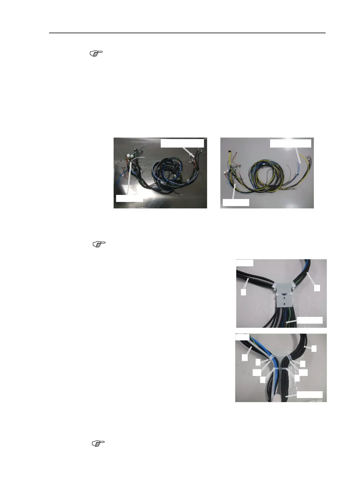
subsequent steps are described with the standard model’s cable unit.
For cleanroom model, a yellow air tube is included in the cable unit.
Cable direction:
Standard
(backward)
The cable unit consists of the
cable A and the cable B.
A: Include the gray colored cable.
B: Include the ground wire (green).
he cable A and the cable B are bundled by eight cable ties.
Hereinafter referred to as below in order from the base side.
A1, A2, …, A8 (cable A)
B1, B2, …, B8 (cable B)
Do not cut off or move the position of the cable tie.
The cable unit will not be able
Fix the cable unit to the cable fixing plate.
Be careful for the following:
Cable ties (AB200) × 4 (1 to 4)
Tightening strength: 85 ± 5 N
able A
Set the A1 of the cable tie to the cable
fixing plate and fix it by using the cable
ties 1 and 2. Make sure that the gray
colored cable is on the plate side.
able B
Set the B1 of the cable tie to the cable
fixing plate and fix it by using the cable
ties 3 and 4. Make sure that the two air
tubes (blue and white) are on the opposite
side of the plate.
Refer to the figure for positions of the cable tie heads.
heads of the cable ties A1 and B1 to set positions.

 Loading...


