Maintenance 4. Cable
192 N6 Rev.2
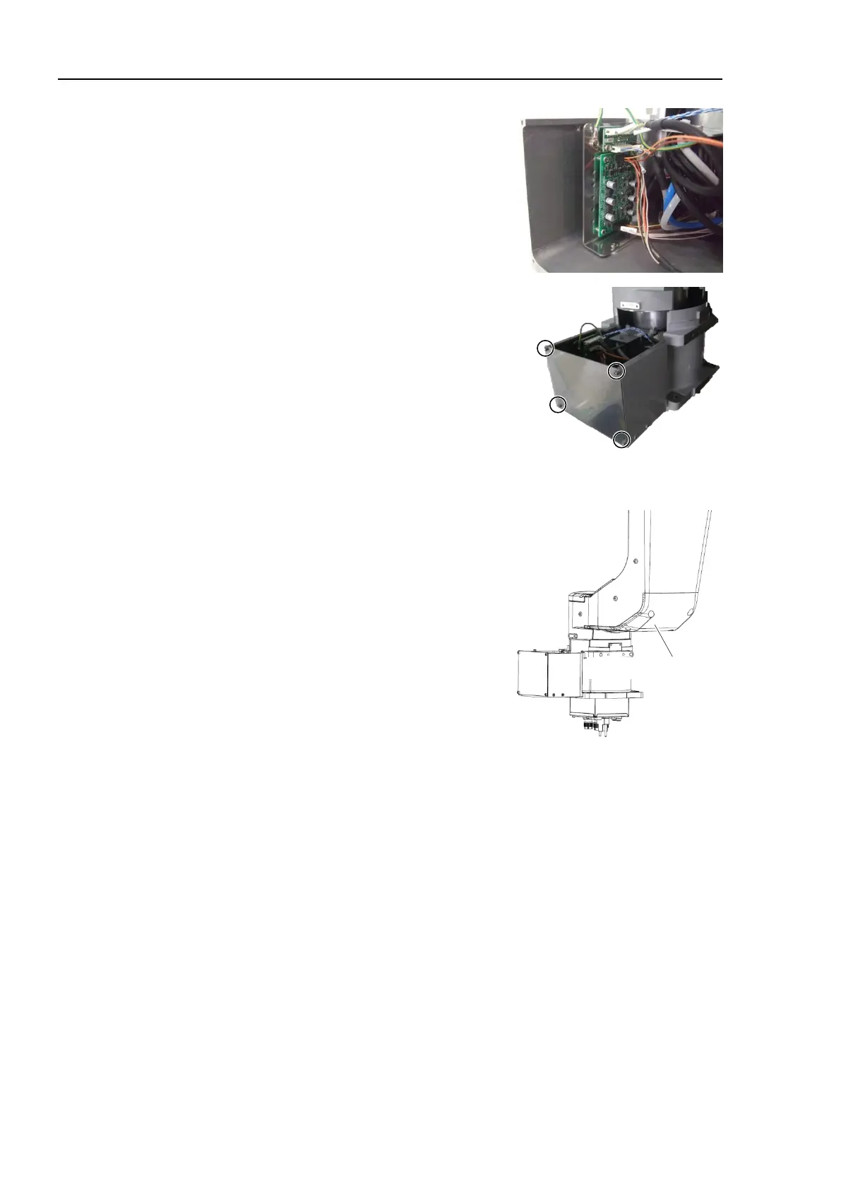
Connect the connectors to the encoder board 1
and
the brake board.
Connectors:
EB01_CN1, EB01_CN3, EB0x_CN2
BRK_CN1, BRK_CN2
Install the base side plate.
Hexagon socket head cap bolts: 4-M4×8
Tightening torque: 4.0 ± 0.2 N·m
Perform the Installation steps
(9) through (52) in Maintenance 4.1 Cable Unit
-A1000*): Cable direction Standard (backward).
Install the Arm #1 outside cover.
Hexagon socket head cap bolts:
8-M5×20 (with plain washer)
Tightening torque: 8.0 ± 0.4 N·m
Install the following covers:
Arm #4 side cover (2 covers)
Joint #4 inside cover Joint #4 outside cover Joint #4 side covers (2 covers)
Arm #3 cover Arm #3 inside cover
Arm #2 cover (2 covers) Joint #2 cover Joint #2 outside cover
Arm #1 inside cover Joint #1 cover
Base cover
For details, refer to Maintenance 3. Covers.
For details, refer to Maintenance 8. Calibration.

 Loading...


