Maintenance 4. Cable
N6 Rev.2 231
subsequent steps are described with the standard model’s cable unit.
For cleanroom model, a yellow air tube is included in the cable unit.
-A850*BR)
pward
Perform the Removal steps (
2) through (6), (8) in Maintenance 4.3 Cable Unit
N6-A850*R): Cable direction Standard (backward).
Disconnect the external short connector.
Perform the Removal steps
(9) through (49) in Maintenance 4.3 Cable Unit
-A850*R): Cable direction Standard (backward).
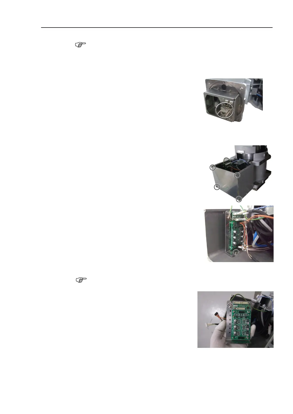
Remove the base side plate.
Hexagon socket head cap bolts: 4-M4×8
Remove the board fixing plate.
Hexagon socket head cap bolts: 2-M3×6
Disconnect the connectors connected to the
encoder board 1 and the brake board.
Connectors:
EB01_CN1, EB01_CN3, EB0x_CN2
BRK_CN1, BRK_CN2
Be careful that the jumper pins on the encoder board do
not come off.
Remove the ground wire terminals fixed on
the board fixing plate.
Cross recessed binding head machine screw:
M4×8
Perform the Removal steps
(56) through (61) in Maintenance 4.3 Cable Unit
-A850*R): Cable direction Standard (backward).

 Loading...


