Maintenance 4. Cable
234 N6 Rev.2
subsequent steps are described with the standard model’s cable unit.
For cleanroom model, a yellow air tube is included in the cable unit.
-A850*BR)
:
Perform the Installation steps
(1) through (8) in Maintenance 4.3 Cable Unit
-A850*R): Cable direction Standard (backward).
Lay down the Manipulator.
Be sure to have at least 2 people to perform the operation.
Pull out the cable unit except the following
cables.
Cables (connectors):
BRK_CN2, EB01_CN3, ground wire
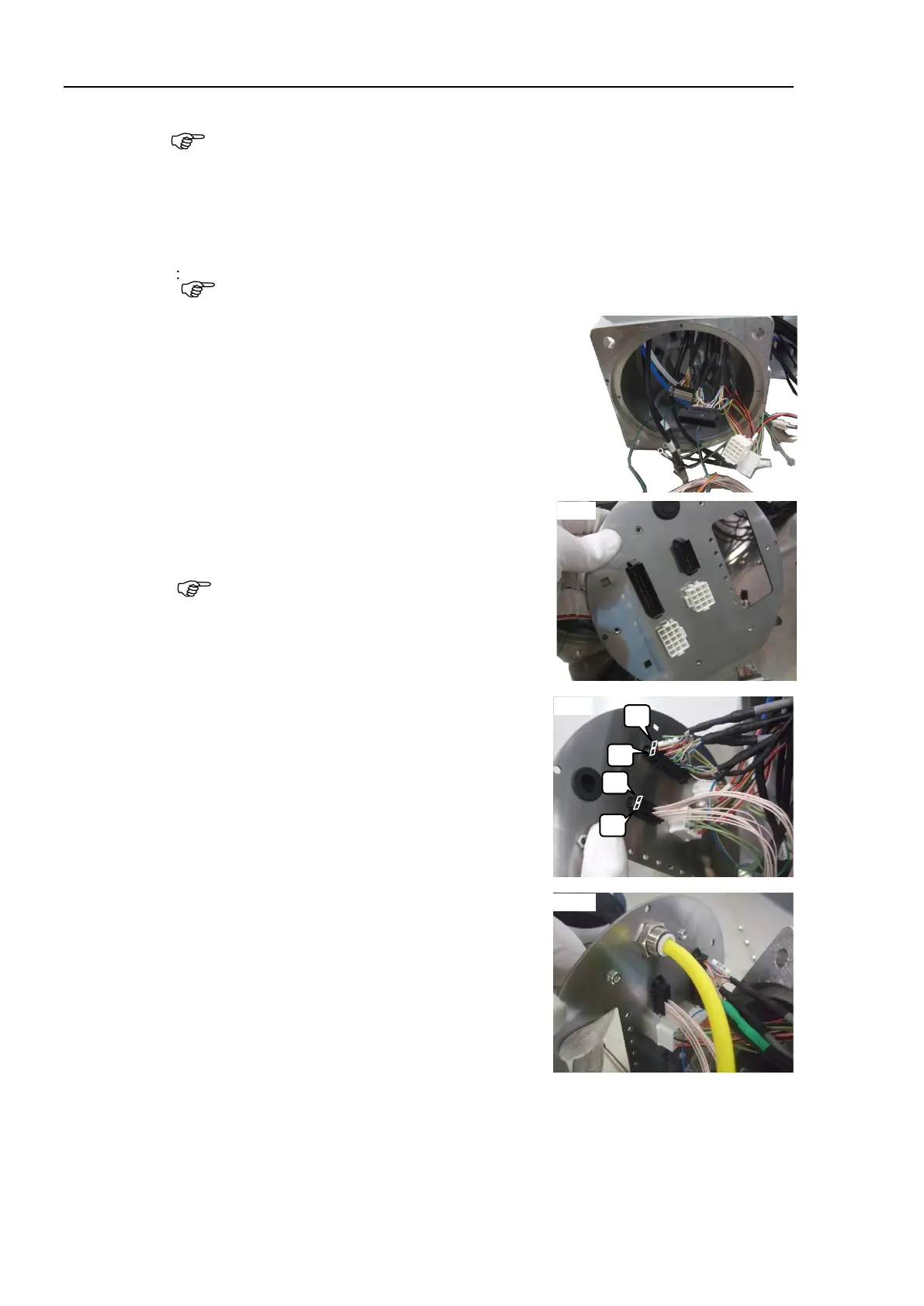
Connect the connectors to the plate part 3
Connectors: X11, X12, X010, BR010
There are the front side and the back side on
the plate part 3.
Be careful for the directions.
Refer to the right picture for installation
direction of black colored connectors (X010,
BR010).
cleanroom
model, connect the yellow air
tube to
the fittings.

 Loading...


