Maintenance 5. Actuator Units
N6 Rev.2 283
-A1000**
the attached O-ring on the Joint #2
Apply a thin coat of grease to the O
-ring.
Grease: SK-1A
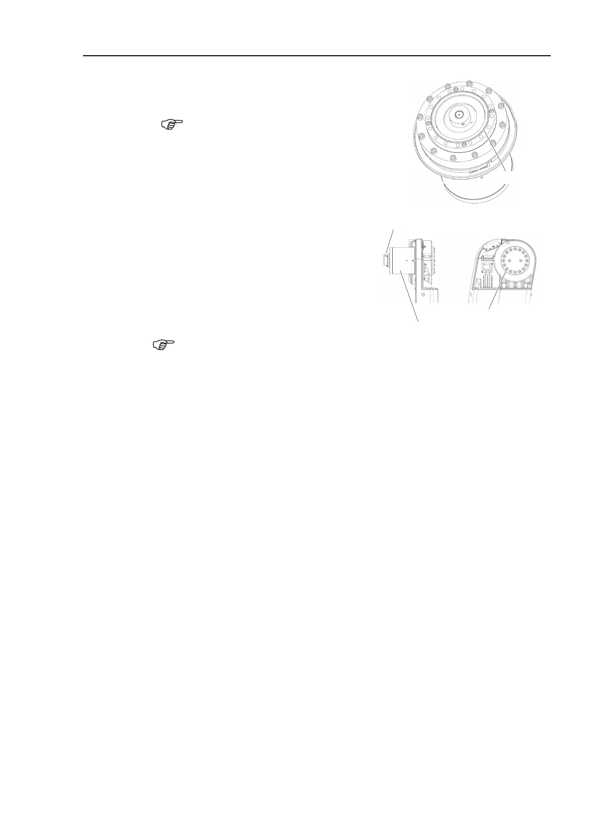
Install the Joint #2 actuator unit to the Arm
#1.
Hexagon socket head cap bolts:
16-M5×35 (with plain washer)
Tightening torque: 10 ± 0.5 N·m
Refer to the figure and install it so that the
cable exit of the actuator unit will be the
opposite side of the base.
16-M5×35(with plain washer)
Cable exit
of the actuator unit
least 2 people to perform the operation since the parts being heavy.
Do not apply excessive shock to the parts.
-ring properly.
Install the robot arm and the cable unit.
For details, refer to the Removal steps (14) through (52) in Maintenance 4.1 Cable
Unit (N6-A1000*): Cable direction Standard (backward).
Install the following covers:
Arm #4 side cover (2 covers), Joint #4 inside cover, Joint #4 outside cover
Joint #4 side cover (2 covers), Arm #3 cover, Arm #3 inside cover
Arm #2 cover (2 covers), Joint #2 cover, Joint #2 outside cover
For details, refer to Maintenance 3. Covers.
.
For details, refer to Maintenance 8. Calibration.

 Loading...


