Maintenance 5. Actuator Units
N6 Rev.2 319
Removal
Joint #5and #6
Unit
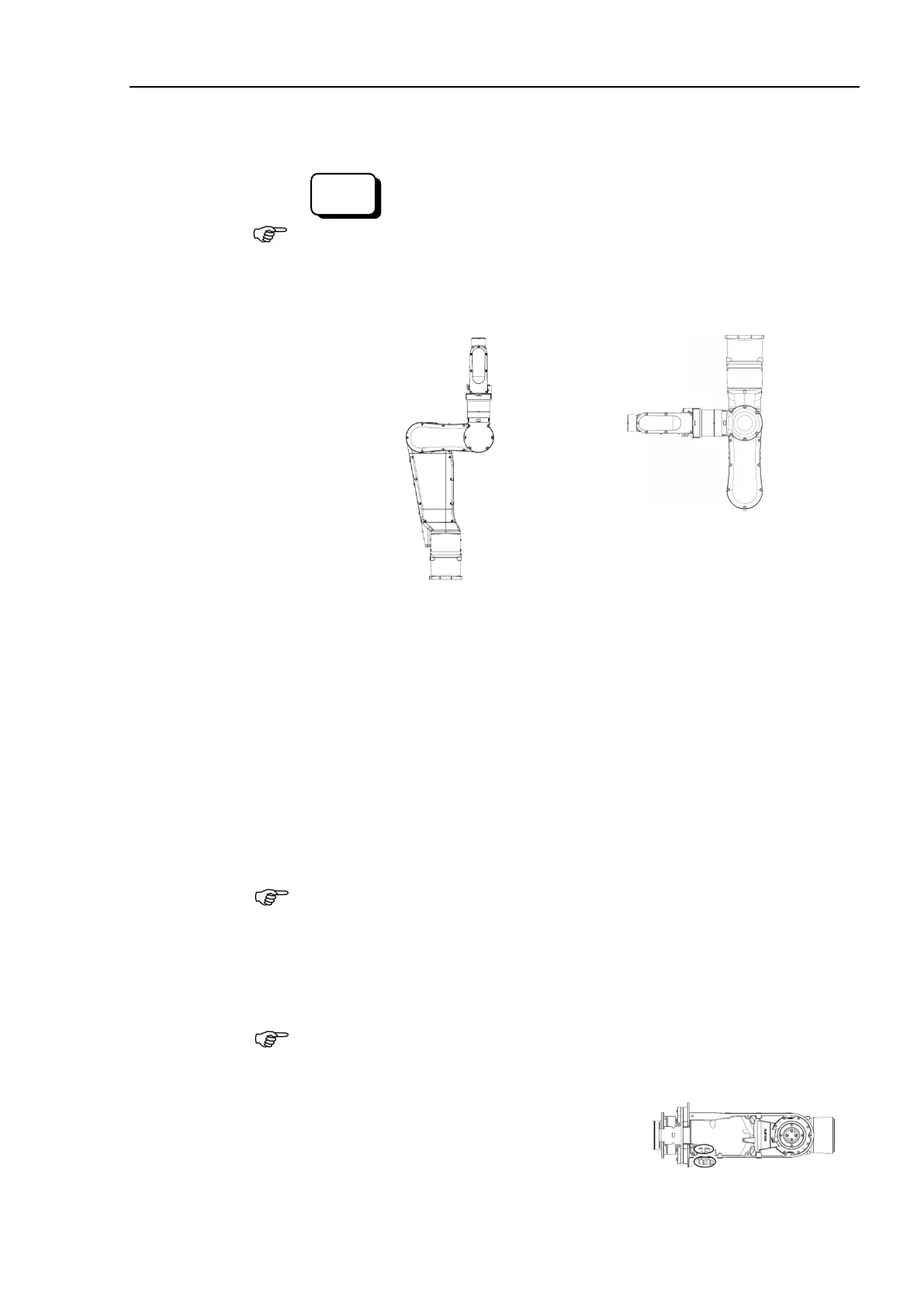
Release the brake on the Joint #3.
When releasing the brake, be careful of the arm falling due to its own weight.
Move the angle of the Arm #3 about 90 degrees from the origin position.
covers.
Arm #4 side cover (2 covers), Joint #4 inside cover, Joint #4 outside cover
For details, refer to Maintenance 3. Covers.
Remove the cable unit from Joint #1 to Arm #4.
For details, refer to the Removal steps (9) through (15) in Maintenance 4.1 Cable
Unit (N6-A1000*): Cable direction Standard (backward).
Remove the Joint #5 motor unit and the timing belt.
For details, refer to the Removal steps (7) and (8) in Maintenance 5.5.1
Replacing the Joint #5 Motor Unit.
on the Joint #5 motor unit to distinguish it later.
(To distinguish the Joint #5 motor unit from the Joint #6 motor unit.)
Remove the Joint #6 motor unit and the timing belt.
For details, refer to the Removal steps (7) and (8) in Maintenance
Replacing the Joint #6 Motor Unit
Place a mark on the Joint #6 motor unit to distinguish it later. (To distinguish the
Joint #6 motor unit from the Joint #5 motor unit.)
Remove the four air tube fittings.

 Loading...


