Maintenance 7. Boards
N6 Rev.2 341
CAUTION
■
Improper jumper pin settings may result in
occurrence of the errors such as below.
Example:
5042: Position error overflow in high power state.
Check the power cable connection, the robot, the driver and the motor.
When replacing the boards, be
careful not to configure them incorrectly.
Installation
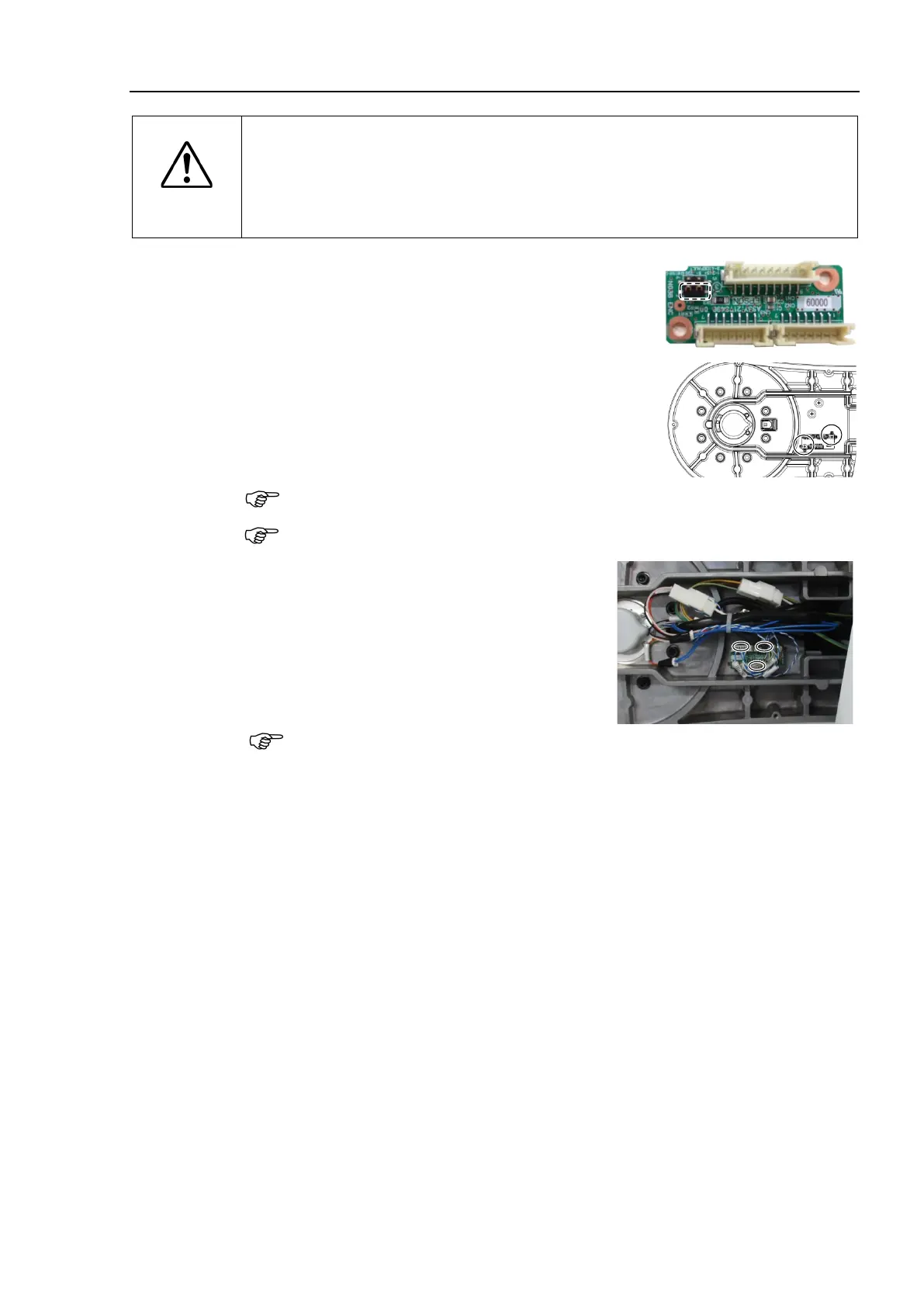
Encoder Board
2
the jumper pin on the encoder
“1-2 short”.
board 2 to the Arm #2.
Cross recessed binding head machine screws:
2-M3×6
Tightening torque: 0.45 ± 0.05 N·m
Be careful not to drop the screws inside the Manipulator while removing them.
Make sure to install as the same direction as the figure.
Connect the connectors to the encoder board 2.
Connectors: EB02_CN1
EB0x_CN2 (Joint #2 side)
EB0x_CN2 (Joint #3 side)
Be careful that the jumper pins on the board do not come off.
(Arm #1 side).
For details, refer to Maintenance 3. Covers.
ON the controller.
Calibrate the Joints #2 and #3.
For details, refer to Maintenance 8. Calibration.

 Loading...


