Maintenance 8. Calibration
N6 Rev.2 353
Also, pay attention to the following points at the encoder initialization.
CAUTION
■
s #1 to Joint #4 have no mechanical stops. If the encoder initialization
is performed with improper posture, the Manipulator moves outside the operation
range.
If the Manipulator was moved outside the operation range, the internal
wiring may be damaged by being twisted or pinched and it may result in
Manipulator malfunction.
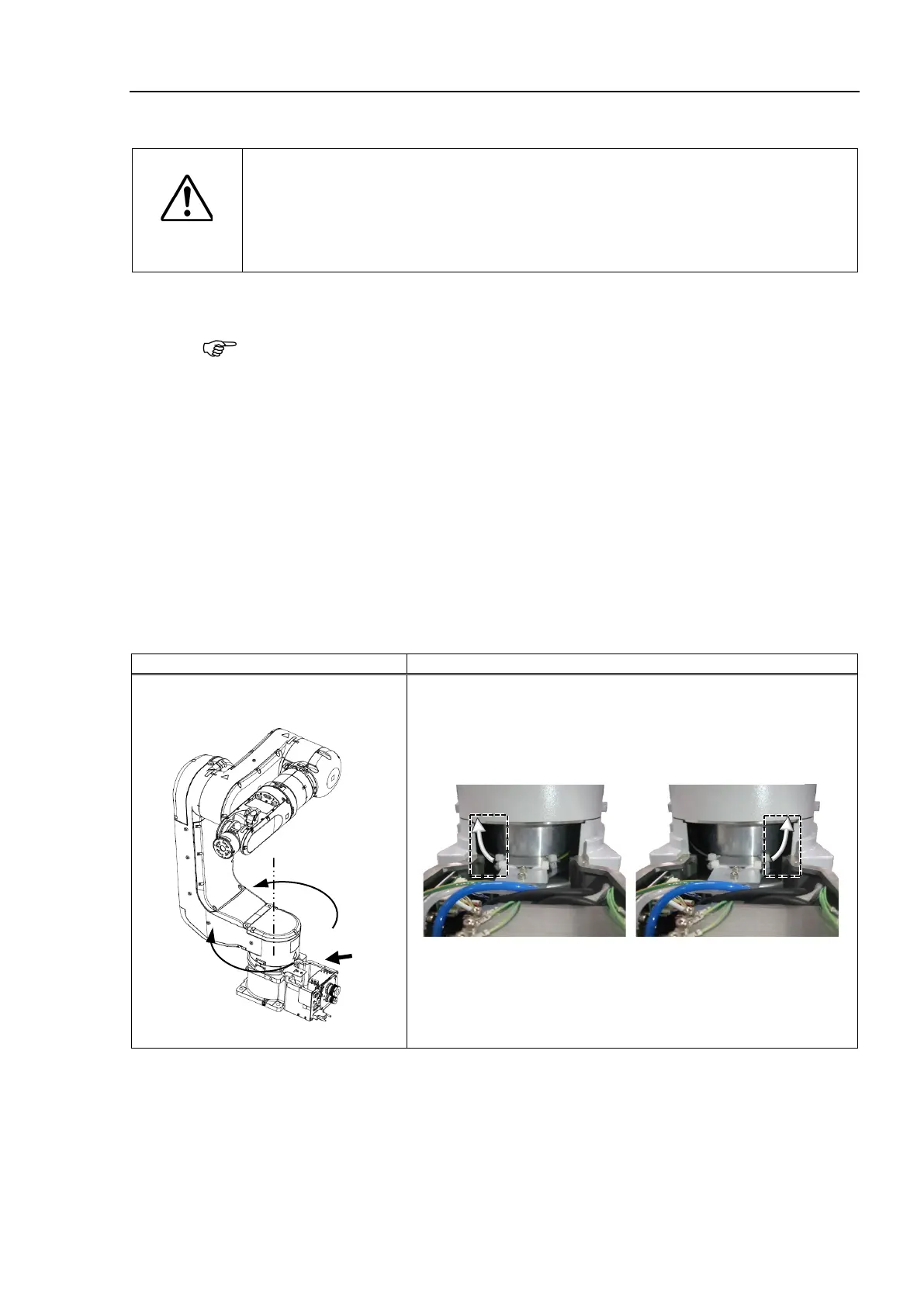
1 to #4 rotates 360 degrees, the Manipulator will be the same posture.
+180 degree and −180 degree is the same.
When you are not sure the current joint angle, check the internal wiring and tubing
(cables).
You can check the cable conditions by removing
the each cover.
Joint #1 : Base cover
Joint #2 : Joint #2 cover (N6-A1000**), Arm #1 inside cover (N6-A850**R)
Joint #3 : Arm #3 inside cover
Joint #4 : Joint #4 inside cover, Joint #4 outside cover
For procedures of the cover removal, refer to Maintenance 3. Covers.
are examples of the cable conditions at ±180 degree posture.
White arrow is an image of the cable.)
N6-A1000**
Joint #1
Cable direction: Arm #1 side

 Loading...


