3.3 Running Mode
3-12
[ 2 ] Settings under PID dancer control
To enable the PID dancer control, you need to set the J01 data to “3.”
Under the PID control, the items that can be specified or checked with and keys are different from those
under the regular frequency control, depending upon the current LED monitor setting. If the LED monitor is set to the
speed monitor (E43 = 0), the item accessible is the primary frequency command; if it is set to any other, the item is
the PID dancer position set point.
Setting the PID dancer position set point with the and keys
(1) Set the J02 data to “0” ( / keys on keypad).
(2) Set the LED monitor to something other than the speed monitor (E43=0) when the inverter is in Running
mode. When the keypad is in Programming or Alarm mode, you cannot modify the PID dancer position set
point with the / key. To enable the PID dancer position set point to be modified with the / key,
first switch to Running mode.
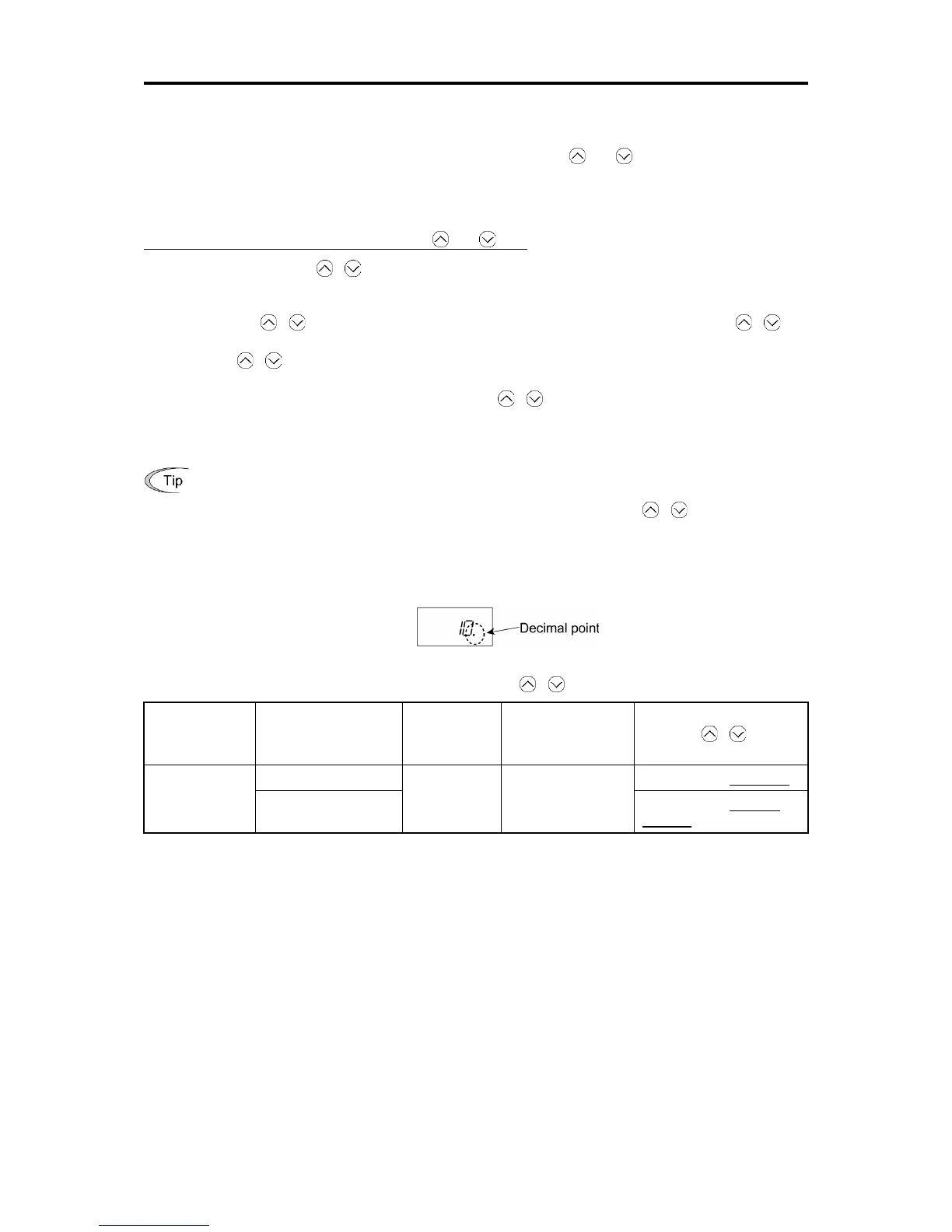
(3) Press the / key to display the PID dancer position set point. The lowest digit and its decimal point blink
on the LED monitor.
(4) To change the PID dancer position set point, press the / key again. The command you have specified
will be automatically saved into the inverter’s internal memory as function code J57 data. It is retained even if
you temporarily switch to another PID command source and then go back to the via-keypad PID command.
Furthermore, you can directly configure the command with function code J57.

 Loading...


