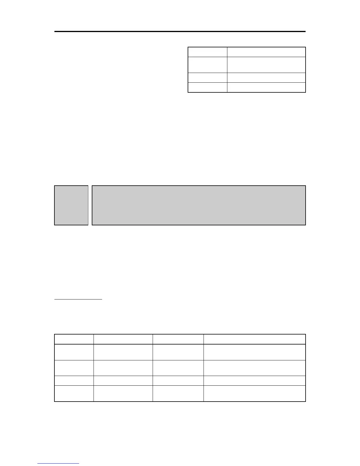
J66 data Operation mode
0
Enabled during constant speed
and deceleration time.
1 Enabled during constant speed
2
Enabled always
■ Timer (J67)
Apply the timer (J67) to prevent the start of the overload stop function due to the instantaneous, unintended load
fluctuation. The overload stop function is activated when the operation condition has continued for specified timer
J67. (if J65=1, 2).
■ Enable overload stop - “OLS” (E01 to E05 = 46)
Turning this terminal command ON enables the overload stop function; turning it OFF disables the function. If “OLS”
is not assigned to any terminal, the overload stop function is always valid.
[ 6 ] Brake control signal
J68 to J70
J71, J72
J95, J96
Brake control signal (Brake-release current, Brake-release frequency/speed and
Brake-release timer)
Brake control signal (Brake-apply frequency/speed and Brake-apply timer)
Brake control signal (Brake-release torque, Brake-apply conditions)
Related function code: A98: Motor 2 (Function selection)
The brake (release/apply) control signal is useful for lift application such as a hoist. This signal is adjustable with
these function codes.
It is possible to set the release and apply conditions based of these signals (current, torque and frequency/speed)
so that a hoisted load does not fall down at the start or stop of the operation, or so that the load applied to the brake
is reduced.
■ Brake control “BRKS” (E20, E21 and E27, data = 57)
This signal outputs a brake control command that releases or applies the brake.
Releasing the Brake
When the inverter output current and output frequency exceeds the specified level for the brake control signal
(J68/J69/J95) for the period specified by J70 (Brake control signal (Brake-release timer)), the inverter judges that
required motor torque is generated and turns the signal BRKS ON for releasing the brake.
This prevents a hoisted load from falling down due to an insufficient torque when the brake is released.
Function code Name Data setting range Remarks
J68 Brake-release current 0.00 to 300.00%: Set the value in percentage (%) of the
inverter rated current.
J69 Brake-release
frequency/speed
0.0 to 25.0 Hz
J70 Brake-release timer 0.00 to 5.00s
J95 Brake-release torque 0.00 to 300.00%
Only available under vector control with
speed sensor.
Note: Resolution of each function code is different from the FRENIC-MEGA and FRENIC-Multi series.

 Loading...


