5.3 Description of Function Codes
5-48
[ 2 ] Setting up a reference frequency using analog input (F01 = 1 to 3, 5)
It is possible to arbitrarily specify a frequency setting from the analog inputs (voltage value to be input to terminal
[12] or terminal [C1] (V2 function) or current value to be input to terminal [C1] (C1 function)) by multiplying them
with the gain and adding the bias. The polarity can be selected and the filter time constant and offset can be
adjusted.
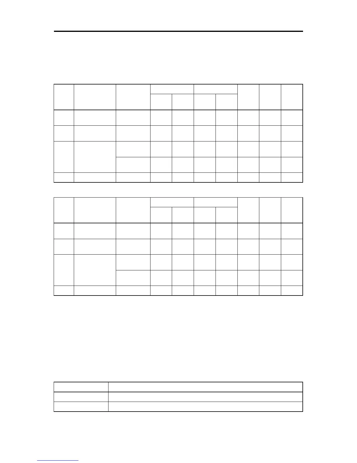
Adjustment constants of frequency setting 1
F01
data
Input terminal Input range
Bias Gain
Polarity
selection
Filter Offset
Bias
Base
point
Gain
Base
point
1 [12]
0 to +10V,
-10 to +10V
F18 C50 C32 C34 C35 C33 C31
2 [C1] (C1 function)
4 to 20 mA
0 to 20 mA
F18 C50 C37 C39 C40 C38 C36
3
[12]+ [C1]
(C1 function)
(Set by result of
addition)
0 to +10V,
-10 to +10V
F18 C50 C32 C34 C35 C33 C31
4 to 20 mA
0 to 20 mA
F18 C50 C37 C39 C40 C38 C36
5 [C1] (V2 function) 0 to +10V F18 C50 C42 C44 C45 C43 C41
Adjustment constants of frequency setting 2
C30
data
Input terminal Input range
Bias Gain
Polarity
selection
Filter Offset
Bias
Base
point
Gain
Base
point
1 [12]
0 to +10V,
-10 to +10V
C55 C56 C32 C34 C35 C33 C31
2 [C1] (C1 function)
4 to 20 mA
0 to 20 mA
C61 C62 C37 C39 C40 C38 C36
3
[12]+
[C1] (C1 function)
(Set by result of
addition)
0 to +10V,
-10 to +10V
C55 C56 C32 C34 C35 C33 C31
4 to 20 mA
0 to 20 mA
C61 C62 C37 C39 C40 C38 C36
5 [C1] (V2 function) 0 to +10V C67 C68 C42 C44 C45 C43 C41
■ Offset (C31, C36, C41)
C31, C36 or C41 configures an offset for an analog voltage/current input. The offset also applies to signals sent
from the external equipment.
■ Filter (C33, C38, C43)
C33, C38, and C43 provide the filter time constants for the voltage and current of the analog input. The larger the
time constant, the slower the response. Specify the proper filter time constant taking into account the response
speed of the machine (load). If the input voltage fluctuates due to line noises, increase the time constant.
■ Terminal [12] Polarity selection (C35)
C35 configures the polarity and therefore the input range for analog input voltage.
C35 data Modes for terminal inputs
0 -10 to +10 V
1 0 to +10 V (Negative value of voltage is regarded as 0 V)

 Loading...


