11.25 PG interface card (OPC-E2-PG3)
11-76
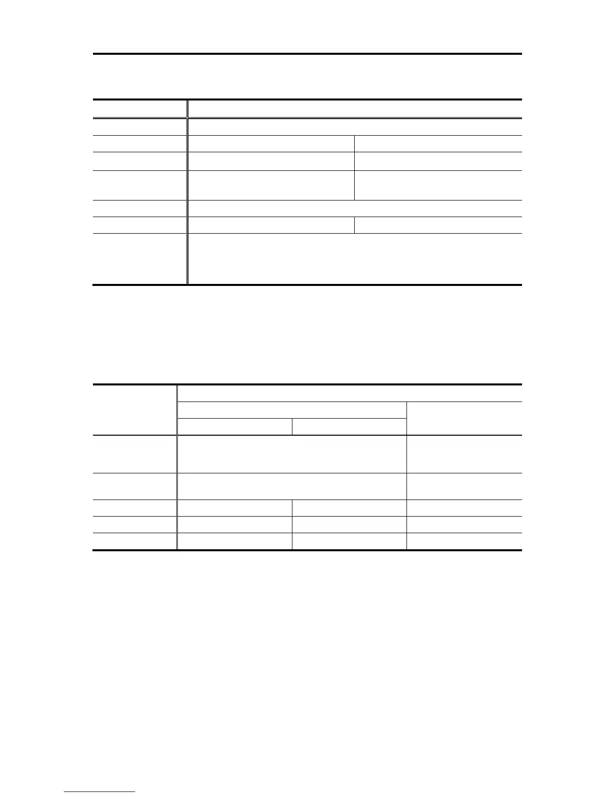
11.25.2 Interface specifications (command side, pulse train interface)
Table 11.25-2
Item specifications
Pulse format A, B and Z-phase pulse trains in incremental format
Pulse type Open collector Push pull (complementary)
frequency 30kHz (duty : 50±10%) 100kHz ( duty : 50±10%)
Wire length *1 20m (66 ft) or less
30m (98 ft) or less (100kHz)
100m (328 ft) or less (30kHz)
pulse threshold High level ≥ 8Vdc, Low level ≤ 3Vdc
Number of pulse 20 to 3600P/R 20 to 3600P/R
PG power supply
+12V±10% / 80mA, +15V±10% / 60mA
If an encoder exceeding the above current has to be connected, it is necessary to
use an external power supply.
The above current is the total value including the PG interface side.
*1: These values are approximate. They might be shorter depending on the wire type or noise environment.
11.25.3 Constraints on standard control circuit terminal
Some control circuit terminals of OPC-E2-PG3 are different from the terminals of the standard specification of
FRENIC-Ace. Different specifications are as follows.
Table 11.25-3
Item
Specifications
Standard control cuircuit terminal OPC-E2-PG3
FRN□□□□E2■-2/4/7GA FRN□□□□E2■-2/4/7GB,-4C
Power supply “PLC”
Power supply for digital input terminals, X1 to X5, FWD
and REV. In addition, it can output 100mA (24V) for
external devices.
Power supply for digital
input terminals only
Degital input “X5”
Available as pulse train input.
Not available as pulse train
input.
Anlog output “FM2” N Y N
CANopen Y N N
RS-485 Y Y N

 Loading...


