EasyManua.ls Logo

Fuji Electric FRENIC-Ace series - Measurement of Electrical Amounts in Main Circuit

Fuji Electric FRENIC-Ace series
788 pages
To Next Page IconTo Next Page
To Previous Page IconTo Previous Page
Loading...
7.5 Measurement of Electrical Amounts in Main Circuit
7-9
MAINTENANCE AND INSPECTION
Chap 7
7.5 Measurement of Electrical Amounts in Main Circuit
Because the voltage and current of the power supply (input, primary circuit) of the main circuit of the inverter and
those of the motor (output, secondary circuit) contain harmonic components, the readings may vary with the type of
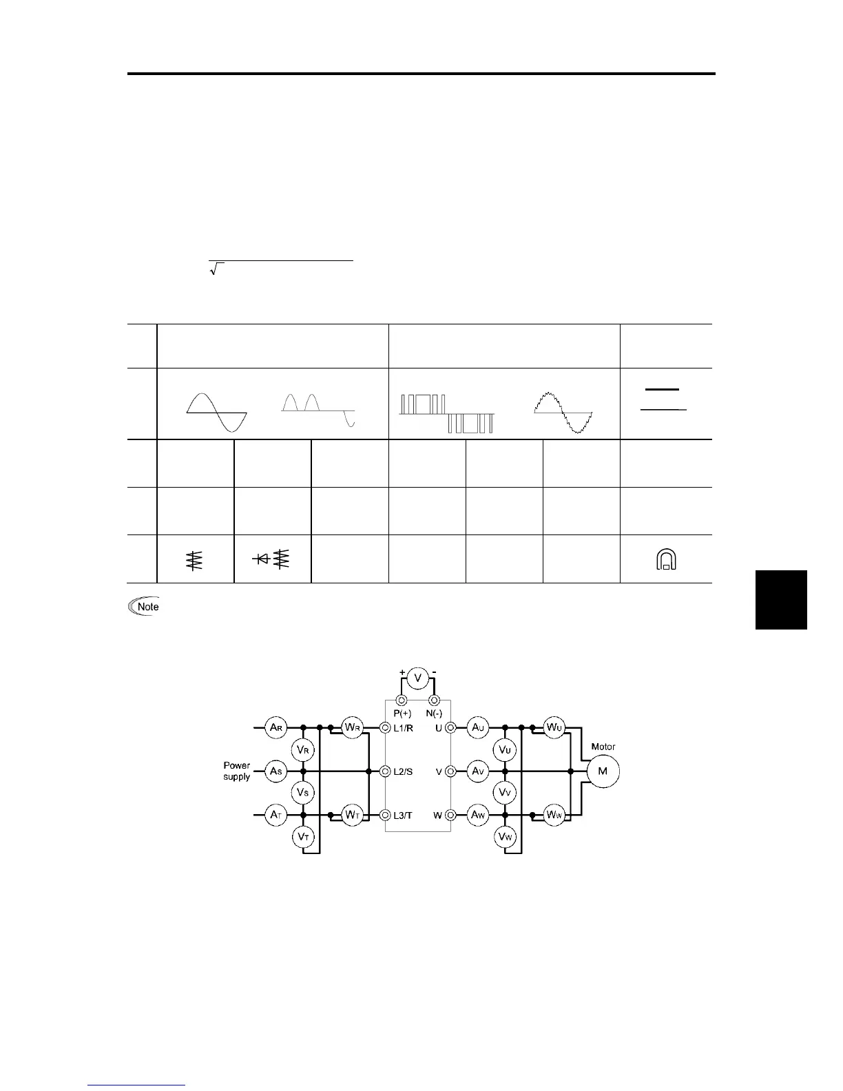
the meter. Use meters indicated in Table 7.5-1 when measuring main circuit.
The power factor cannot be measured by a commercially available power-factor meter that measures the phase
difference between the voltage and current. To obtain the power factor, measure the power, voltage and current on
each of the input and output sides and use the following formula.
Three-phase input
%100×
(A)Current×(V)Voltage×3
(W)powerElectric
=factorPower
Table 7.5-1 Meters for Measurement of Main Circuit
Item
Input (primary) side Output (secondary) side
DC link bus
voltage
(P(+)-N(-))
Waveform
Voltage
Current
Voltage
Current
Name of
meter
Ammeter
AR, AS, AT
Voltmeter
VR, VS, VT
Wattmeter
WR, WT
Ammeter
AU, AV, AW
Voltmeter
VU, VV, VW
Wattmeter
WU, WW
DC voltmeter V
Type of
meter
Moving iron
type
Rectifier or
moving iron
type
Digital
AC power
meter
Digital AC
power meter
Digital AC
power meter
Digital AC
power meter
Moving coil type
Symbol
of meter
It is not recommended that meters other than a digital AC power meter be used for measuring the output
voltage or output current since they may cause larger measurement
errors or, in the worst case, they may
be damaged.
Figure 7.5-1 Connection of Meters

Table of Contents

Related product manuals