9.2 CANopen Communication
9-21
COMMUNICATION FUNCTIONS
Chap 9
[ 5 ] Communication parameters of transmit PDO
(1) Communication parameters
Set the property of each transmit PDO (TPDO). The Table 9.2-11 lists appropriate objects.
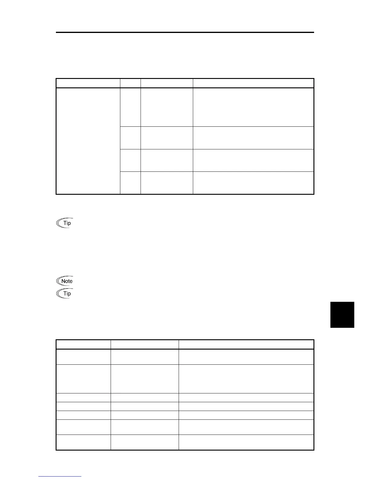
Table 9.2-11 Communication Parameters of Transmit PDO and Default Values
Index Sub Name Description
0x1800 TPDO No.1
0x1801 TPDO No.2
0x1802 TPDO No.3
1 COB-ID Set CAN ID of each PDO and validity
Default value:
TPDO No.1: 0x180 + node ID
TPDO No.2: 0x280 + node ID
TPDO No.3: 0x380 + node ID
2 Transmission type Specify the transmission timing (Table 9.2-12)
Default value: 255 (transmit data if the data
changes)
3 Inhibit time
Specify the minimum interval (unit: 0.1 ms) to next
transmission.
Default value: 100 (10.0 ms)
*
5 Event timer
Specify periodical transmission time (ms). Valid
when the transmission type is 254/255
Default value: 0 (no operation)
*
*: The resolution of timer setting value is 2 ms. If an odd value is specified, the value assumed is the following
higher even value. For example, if the timer is set to 119 ms, the value is assumed to be 120 ms.
The value changed of the objects listed in the Table 9.2-11 is held even if inverter is turned OFF.
(2) COB-ID
Specify 11 bit CAN ID value for each PDO. The default value changes according to the node ID. (Example: If the
node ID of inverter is one, TPDO No.2 COB-ID = 0x281). If the most significant bit (31th bit) is set to one, the
TPDO will be invalid.
It is possible to change COB-ID only when the PDO is invalid.
CAN ID is 11 bit. The bits 11 to 30 are fixed at zero. (Only the standard frame is supported.)
(3) Transmission type
Set the transmission timing to the master for the transmit PDO. The Table 9.2-12 lists the settings.
Table 9.2-12 Transmission Type Setting of Transmit PDO
Transmission type Name Action
0 Acyclic Synchronous
When the data is changed, transmits PDO immediately
after receiving a Sync signal
1-240 Cyclic Synchronous
Transmits PDO every 1 to 240 times a sync signal is
received.
(Example: (if it is set to 10, transmits PDO every 10
times a sync signal is received)
241-251 Reserved -
252 Synchronous RTR only No operation *
253 Asynchronous RTR only No operation *
254 Asynchronous1
Transmits PDO periodically at the time specified by
Event timer
255 Asynchronous2
Transmit PDO upon data change and at the time
specified by Event timer
*: The CANopen communication of inverter does not support the CAN’s remote frame.

 Loading...


