6.3 If an Alarm Code Appears on the LED Monitor
6-3
TROUBLESHOOTING
Chap 6
6.3 If an Alarm Code Appears on the LED Monitor
6.3.1 Alarm code list
When an alarm is detected, check the alarm code displayed on 7-segment LED of keypad.
When one alarm code has more than one cause, alarm subcodes are provided to make it easy to identify the
cause. When there is only one cause, the alarm subcode is displayed as “-” and described as “-.”
* See (Chapter 3 “3.4.6 Reading alarm information”) for the method of checking the alarm codes.
* With regard to alarm details having alarm subcodes name “For manufacturer”, inform the alarm subcodes, too,
when contacting Fuji Electric or requesting an inverter repair.
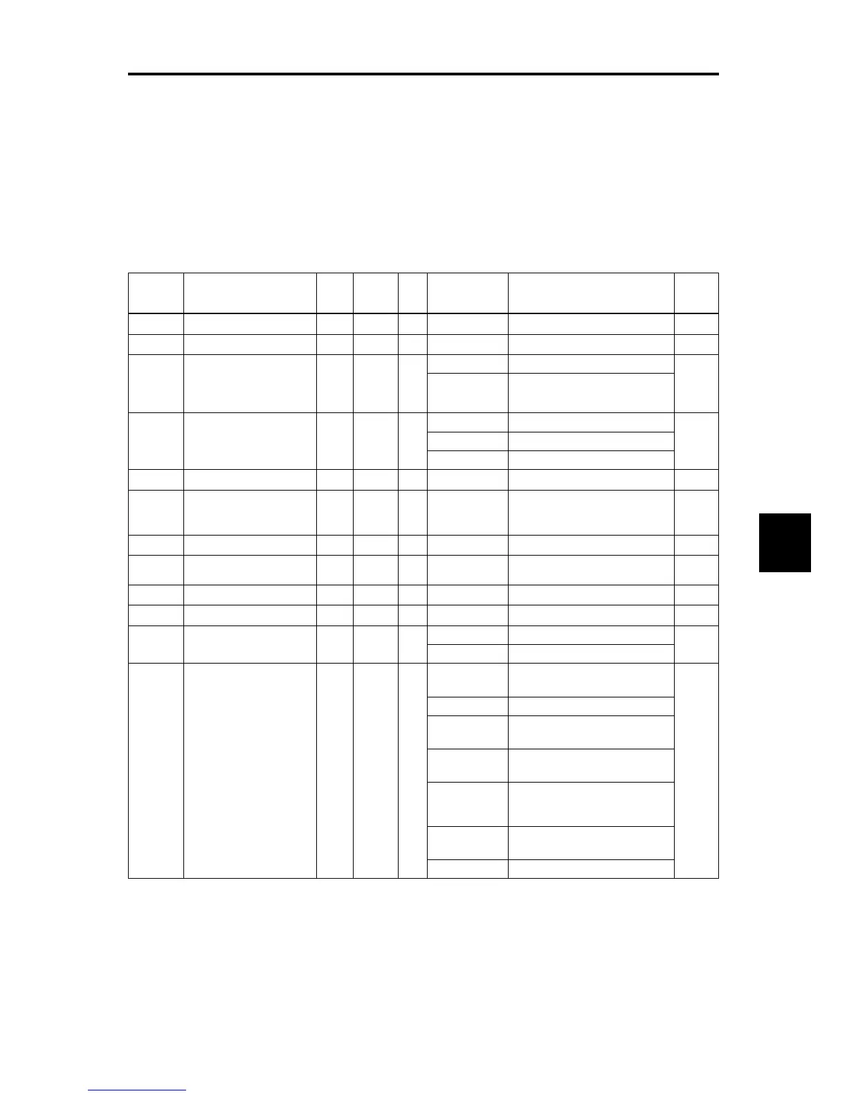
Table 6.3-1 Various failure detections (Heavy failure objects)
Alarm code Alarm code name
Heavy
failure
object
Light
alarm
selectable
Alarm subcode* Alarm subcode name
page
cof
PID feedback wire break Y Y — — — 6-6
dba
Braking transistor broken Y — — — — 6-6
dbh
Braking resistor overheat
(FRN0115E2■-2 or below
/FRN0011E2■-7 or below
/FRN0072E2■-4 or below)
Y Y Y
0 DB resistor overheat
6-6
1 For manufacturer
ecf
EN circuit failure Y
—
—
—
—
—
—
10 ASIC alarm for functional safety
6-7
3000 Erroneous detection of STO input
Other than above For manufacturer
ecl
Customizable logic failure Y — — — — —
ef
Ground fault
(FRN0085E2■-4 or
above)
Y — — — — 6-7
er1
Memory error Y — — 1 to 16 For manufacturer 6-7
er2
Keypad communications
error
Y — — 1 to 2 For manufacturer 6-8
er3
CPU error Y — — 1 to 9000 For manufacturer 6-8
er4
Option communications error Y Y — 1 For manufacturer 6-8
er5
Option error Y Y —
0 Time-out
6-8
1 to 10 For manufacturer
er6
Operation error Y — —
1
STOP key priority/forced stop
(STOP terminal)
6-9
2 Start check function
3
Start check function
(when operation is permitted)
4
Start check function
(when reset is turned on)
5
Start check function
(when the power recovers in
powering on)
6
Start check function
(TP connection)
8 to 14 For manufacturer

 Loading...


