[ 3 ] Transmit PDO (from inverter to master)
(1) Transmit PDO No.1
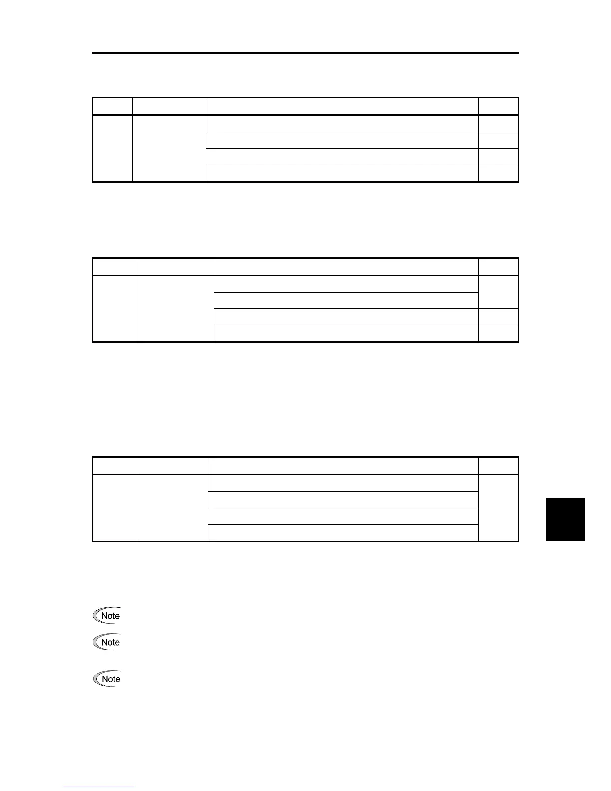
PDO No. Default COB-ID Name Re-map
1 0x180+Node ID Status word (Default) Yes
User-defined Yes
User-defined Yes
User-defined Yes
Statusword: Display the status of state machine with DSP 402
For information about Statusword and state machine with DSP 402, refer to “9.2.10 [ 1 ] Operation according
to CANopen’s drive profile (DSP 402)”.
(2) Transmit PDO No.2
PDO No. Default COB-ID Name Re-map
2 0x280+Node ID
Status word (Default) Yes
vl control effort (r/min) (Default)
User-defined Yes
User-defined Yes
Statusword: Display the status of state machine with DSP 402
vl control effort: Monitor output speed (r/min)
For information about Statusword and vl control effort, refer to “9.2.10 [ 1 ] Operation according to
CANopen’s drive profile (DSP 402)”.
(3) Transmit PDO No.3
This PDO is the ability to read data from the function code that is specified in advance. There are four types of
mapped function codes.
PDO No. Default COB-ID Name Re-map
3 0x380+Node ID Reading function code 1 (function code data specified by y29/o48) No
Reading function code 2 (function code data specified by y30/o49)
Reading function code 3 (function code data specified by y31/o50)
Reading function code 4 (function code data specified by y32/o51)
For information on y29 to y32/o48 to o51, refer to “9.2.5 [ 2 ] Receive PDO (from master to inverter)”, “(4)
How to set the inverter function codes y25 to y32/o40 to o43, o48 to o51 and Indexes 5E00, 5E01”.
For information about data format of the mapped inverter function codes, refer to RS-485 Communication
User’s Manual, Chapter 5, “5.2 Data Format”.
The object indexes 5E01 sub 1 to 4 can map the inverter function codes. In this case, the mappings
become effective immediately after the change. However, if the inverter is restarted or the ResetNode
service is issued, the mappings with

 Loading...


