2.2 Wiring
2-42
2.2.6 Control circuit terminals (common to all models)
[ 1 ] Screw specifications and recommended wire size (control circuit terminals)
The screw specifications and wire sizes to be used for control circuit wiring are shown below.
The control circuit terminal board differs depending on the destination.
Table 2.2-28 Screw Specifications and Recommended Wire Sizes
Terminal symbol
Screw specification
Allowable wire
sizes
Driver
(shape of tip)
insert wire
Size Tightening torque
30A, 30B, 30C
EN1, EN2
M3
0.5 N·m
(4.43 lb-in)
0.14 to 1.5 mm
2
(AWG26 to 16)
Minus
(0.6mm×3.5mm)
6 mm
(0.24 in)
A1
*1
Others M2
0.19 N·m
(1.68 lb-in)
0.25 to 1 mm
(AWG24 to 18)
Minus
(0.4mm×2.5mm)
5 mm
(0.20 in)
φ1.6
* Recommended rod terminal: Phoenix Contact Refer to Table 2.2-29 for details.
*1 Defined according to IEC/EN 60947-1.
Table 2.2-29 Recommended Rod Terminals
Screw size Wire size
Type
With insulating collar Without insulating collar
M3
M2
0.25 mm
2
(AWG24) AI 0.25-6 BU A 0.25-7
0.34 mm
(AWG22) AI 0.34-6 TQ A 0.34-7
0. 5 mm
(AWG20) AI 0.5-6 WH A 0.5-6
0.75 mm
2
(AWG18) AI 0.75-6 GY A 0.75-6
1 mm
2
(AWG18) AI 1-6 RD A 1-6
1.5 mm
(AWG16) AI 1.5-6 BK A 1.5-7
Note) When sizes exceeding the recommended wire sizes are used, the front cover may be pushed outward
depending on the number of wires, causing erroneous operation of the keypad.
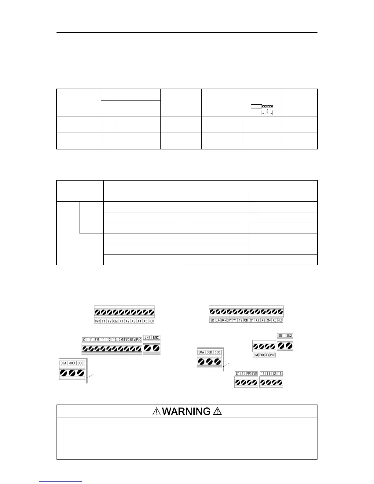
[ 2 ] Terminal layout diagram (control circuit terminal)
The following terminals may have high voltage when the power is ON.
Control terminals: AUX-contact (30A, 30B, 30C)
Insulation level
Contact output – control circuit : Enhanced insulation (overvoltage category II, degree of contamination 2)
Risk of electric shock exists
Enhanced insulation
(Max.
250 VAC overvoltage category II, degree of contamination 2)
Enhanced insulation
(Max.
250 VAC overvoltage category II, degree of contamination 2)

 Loading...


