5.2 Function Codes Table
5-4
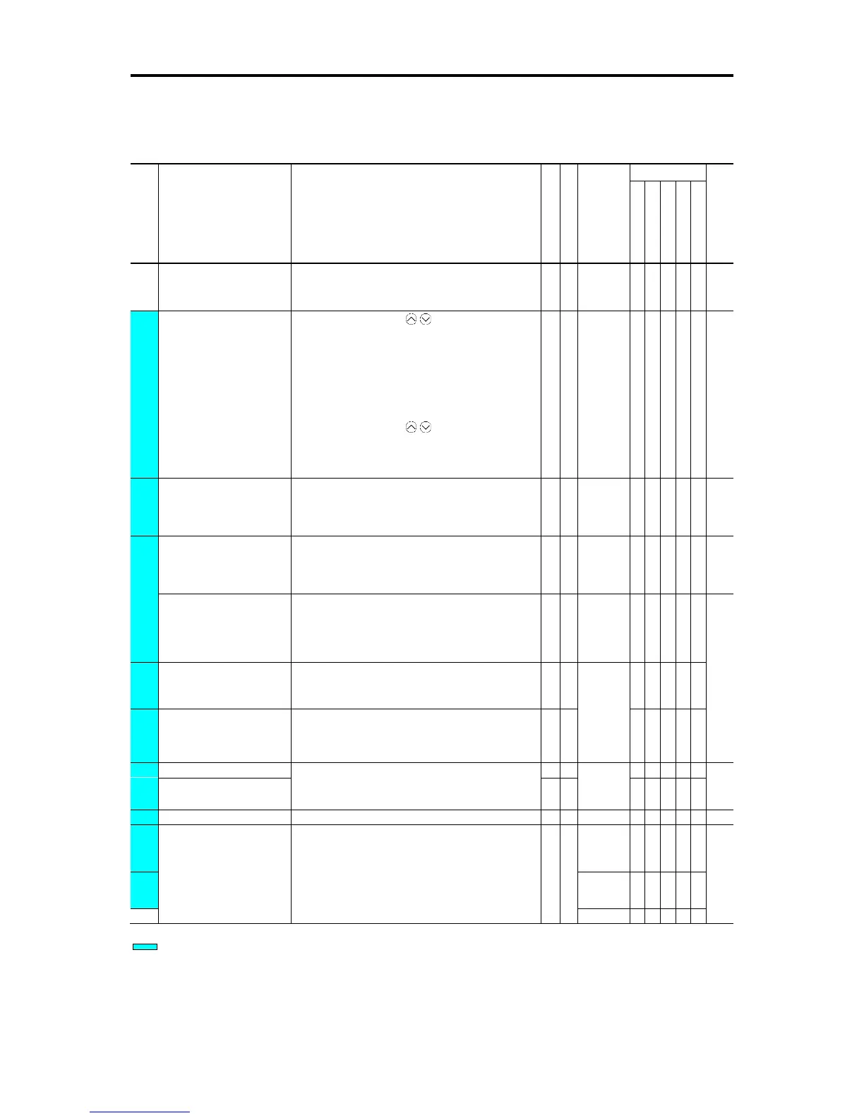
5.2.2 Function codes table
The table of function codes to be used in FRENIC-Ace is shown below.
■ F codes: Fundamental Functions (Basic function)
Code
Name Data setting range
Change when running
Data copying
Factory
Default
0: No data protection, no digital setting protection
1: With data protection, no digital setting protection
2: No data protection, with digital setting protection
3: With data protection, with digital setting protection
0: Keypad key operation ( / key)
1: Analog voltage input (Terminal [12])
(from 0 to ±10 VDC)
2: Analog current input (Terminal [C1] (C1 function))
(4 to 20mA DC, 0 to 20mA DC)
3: Analog voltage input (Terminal [12]) + Analog current
input (Terminal [C1] (C1 function))
5: Analog voltage input (Terminal [C1] (V2 function))
(0 to 10 VDC)
7: UP/DOWN control
8: Keypad key operation ( / key)
(With balanceless bumpless)
10: Pattern operation
11: Digital input/output interface card (option) *5
(rotation direction input: terminal block)
1: External signal (digital input)
2: Keypad operation (forward rotation)
3: Keypad operation (Reverse rotation)
Maximum output frequency 1
J:50.0
AUK:60.0
400V class
(output voltage proportional to power voltage)
80 to 240 V : AVR operation (200V class)
160 to 500V : AVR operation (400V class)
J:200
AK:220
U:230
400V class
80 to 240V : AVR operation (200V class)
160 to 500V : AVR operation (400V class)
* 0.00 is for acceleration and deceleration time cancel
(when performing soft-start and stop externally)
0.0 to 20.0% (% value against base frequency voltage 1)
Electronic thermal overload
protection for motor 1
(Select motor characteristics)
1: Enable (For a general-purpose motor with self-cooling
fan)
2: Enable (For an inverter-driven motor (FV) with
separately powered cooling fan)
(Overload detection level)
0.00 (disable), current value of 1 to 135% of inverter rated
(Inverter rated current dependent on F80)
Factory default
A (For Asia), C (for China), E (for Europe), U (For USA), J (for Japan), K (for Korea)
indicates quick setup target function code.
*2: Factory defaults are depended on motor capacity. Refer to “5.2.3 Factory default value per applicable electric motor capacitance”.
*3: The motor rated current is automatically set. Refer to “5.2.4 Motor constant”.
*4: 5.0min for inverters of nominal applied motor 22kW or below; 10.0min for those of 30kW or above.
*5: Available at ROM version 0300 or later.
*10: 6.00s for inverters of nominal applied motor 22kW or below; 20.0s for those of 30kW or above.

 Loading...


