2.1 Installation
2-2
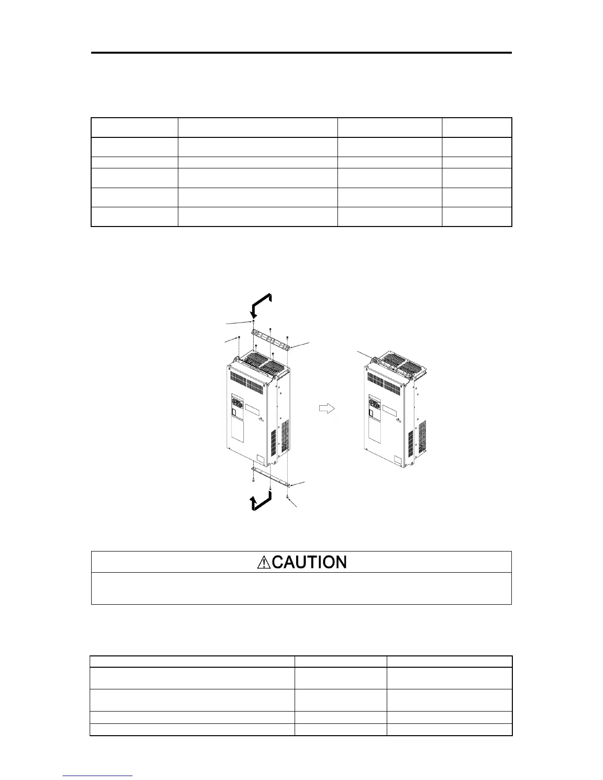
To install the FRN0085E2■-4 inverter with external cooling, change the mounting position of the mounting bases
following the procedure in Figure 2.1-3.
As the type and number of screws differ by inverter type, please review Table 2.1-2.
Table 2.1-2 Type and Number of Screws, and Tightening Torque
Inverter type Mounting base fixation screw Case attachment screw
FRN0085E2■-4
to FRN0168E2■-4
M6×20 (5 screws on top, 3 screws on bottom) M6×20 (2 screws on top only)
5.8 (51.3)
FRN0203E2■-4
20 (3 screws on top and bottom each)
12 (3 screws on top only)
M5×12 (7 screws on top and bottom each) M5×12 (7 screws on top only)
3.5 (31.0)
FRN0361E2■-4
M5×16 (7 screws on top and bottom each) M5×16 (7 screws on top only)
3.5 (31.0)
FRN0520E2■-4
to FRN0590E2■-4
M5×16 (8 screws on top and bottom each) M5×16 (8 screws on top only)
3.5 (31.0)
1) Remove all of the mounting base fixation screws and the case attachment screws on the top of the inverter.
2) Fix the mounting bases to the case attachment screw holes using the mounting base fixation screws. A few
screws should remain after changing the position of the mounting bases.
3) Change the position of the mounting bases on the bottom side following the procedure in 1) and 2).
Mounting base fixation screw
Mounting base
(upper side)
Mounting base (lower side)
Mounting base
fixation screw
Figure 2.1-3 Method to Change the Mounting Base Positions
Use the specified screws in changing the mounting bases.
Risk of fire and risk of accidents exist
■ Inverter unit installation screw size
Select the bolt size, considering the thickness of the mounting feet and installation surface so that the bolt
protrudes from the nut by 2 threads or more.
200V class:FRN0030/0040E2■-2
400V class:FRN0022/0029E2■-4
M5 (4 screws) 3.5 (31.0)
200V class:FRN0056/0069E2■-2
M8 (4 screws) 13.5 (119)
400V class:FRN0240E2■-4 to FRN0415E2■-4
M12 (4 screws) 48 (425)
400V class:FRN0520E2■-4 to FRN0590E2■-4
M12 (6 screws) 48 (425)

 Loading...


