2.2 Wiring
2-7
INSTALLATION AND WIRING
Chap 2
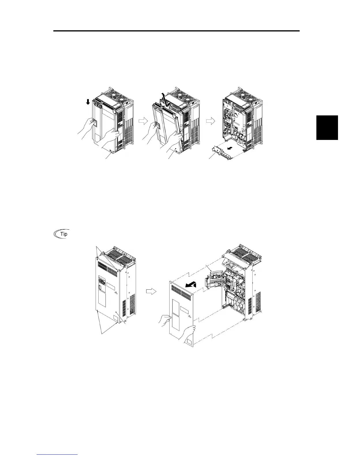
(3) Types FRN0088E2
1) Loosen the screws of the front cover. Hold both sides of the front cover with the hands, slide the cover
downward, and pull. Then remove it to the upward direction.
2) Push the wiring guide upward and pull. Let the wiring guide slide and remove it.
3) After routing the wires, attach the wiring guide and the front cover reversing the steps above.
Figure 2.2-5 Removal of the Front Cover and the Wiring Guide (for FRN0072E2■-4)
(4) Types FRN0085E2
or above
1) Loosen the screws of the front cover. Hold both sides of the front cover with the hands and slide it upward to
remove.
2) After routing the wires, align the front cover top edge to the screw holes and attach the cover reversing the steps
in Figure 2.2-6.
Open the keypad case to view the control printed circuit board.
Tightening torque: 1.8 N·m (15.9 Ib-in) (M4)
3.5 N·m (31.0 Ib-in) (M5)
Figure 2.2-6 Removal of the front cover (for FRN0203E2■-4)
Front cover attachment screw
Push upward and pull.
Let the guide slide.

 Loading...


