FUNCTION CODES
Chap 5
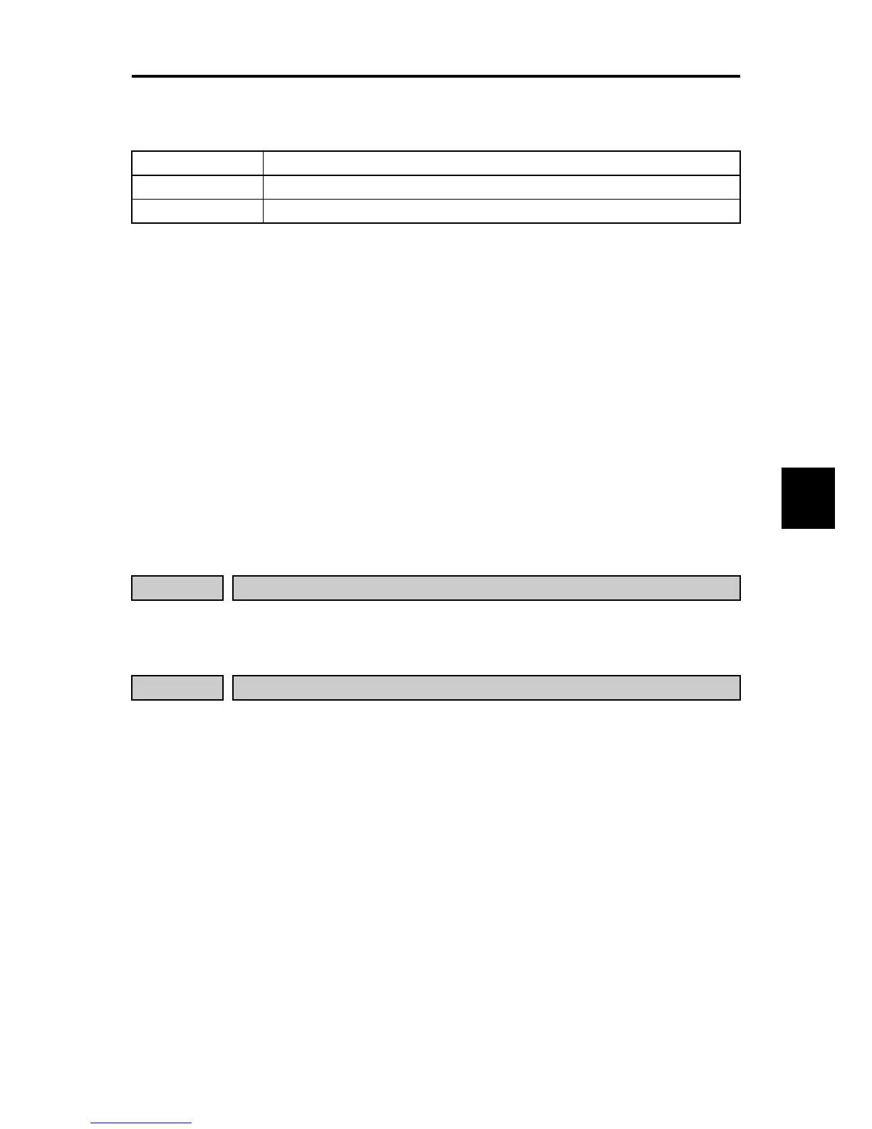
■ Servo lock (Gain) (J97)
J97 specifies the gain of the servo lock positioning to adjust the stop behavior and shaft holding torque against an
external force. If the mechanical stiffness is not high, J97 is difficult to set larger.
J97 Small ↔ Large
Stop behavior Response slow, but smooth ↔ Response quick, but hunting might occur.
Shaft holding torque Small ↔ Large
• Data setting range: 0.000 to 9.999 (times) (Factory default is 0.010)
Note: Resolution of J97 and factory default value is different from the FRENIC-MEGA series.
■ Notes for using servo lock
(1) Positioning control error
ero
If a positioning error exceeds the value equivalent to four rotations of the motor shaft when the inverter is
servo locked, the inverter issues a positioning control error signal
ero
.
(2) Stop frequency (F25) under servo lock
Since servo lock starts when the output frequency is below the stop frequency (F25), it is necessary to
specify such F25 data that does not trigger
ero
(that is, specify the value equivalent to less than 4 rotations
of the motor shaft).
Stop frequency (F25) < (4 × Gain (J97) × Maximum frequency)
(Example) When Gain (J97) = 0.01 and Maximum frequency (F03) = 60 Hz, specify F25 data < 2.4 Hz.
(3) The following functions are ignored in the servo lock mode:
• Frequency/speed control specified with the stop frequency
• Rotation direction limitation
J105 to J107

 Loading...


