FUNCTION CODES
Chap 5
■ P(Gain) (d03/A45/b45/r45), I(integral time) (d04/A46/b46/r46)
d03 and d04 specify the gain and integral time of the speed regulator (PI processor), respectively.
• Data setting range: (d03) 0.1 to 200.0 (times)
(d04) 0.001 to 9.999 (s), 999 (Cancel integral term)
P(Gain)
Definition of “P gain = 1.0” is that the torque command is 100% (100% torque output of each inverter capacity)
when the speed deviation (reference speed – detected speed) is 100% (equivalent to the maximum speed).
Determine the P gain according to moment of inertia of machinery loaded to the motor output shaft. Larger moment
of inertia needs larger P gain to keep the flat response during whole operation.
Specifying a larger P gain improves the quickness of control response, but may cause a motor speed overshooting
or hunting (undesirable oscillation of the system). Moreover, mechanical resonance or vibration sound on the
machine or motor could occur due to excessively amplified noise. If it happens, decreasing P gain will reduce the
amplitude of the resonance/vibration. A too small P gain results in a slow inverter response and a speed fluctuation
in low frequency, which may prolong the time required for stabilizing the motor speed.
I(Integral time)
Specifying a shorter integral time shortens the time needed to compensate the speed deviation, resulting in quick
response in speed. Specify a short integral time if quick arrival to the target speed is necessary and a slight
overshooting in the control is allowed; specify a long time if any overshooting is not allowed and taking longer time
is allowed.
If a mechanical resonance occurs and the sound from the motor or gears is abnormal, setting a longer integral time
can transfer the resonance point to the low frequency zone and suppress the resonance in the high frequency
zone.
■ FF(Gain) (d05/A47/b47/r47)
The inverter operates the feed forward (FF) control that adds the acceleration torque calculated from the variation
of speed command to torque command directly.
The PI control of ASR is feed back control and it makes the compensation operation against the result (actual
speed detection value). Therefore it can control against the disturbance or the uncertain characteristic of controlled
object also. However it becomes a follow-up control even if the variation of speed command is already-known.
The feed forward control can calculate the torque command related to the already-known variation of speed
command.
This is the function code that can make the feed forward control.
• Data setting range: 0.00 to 99.99s
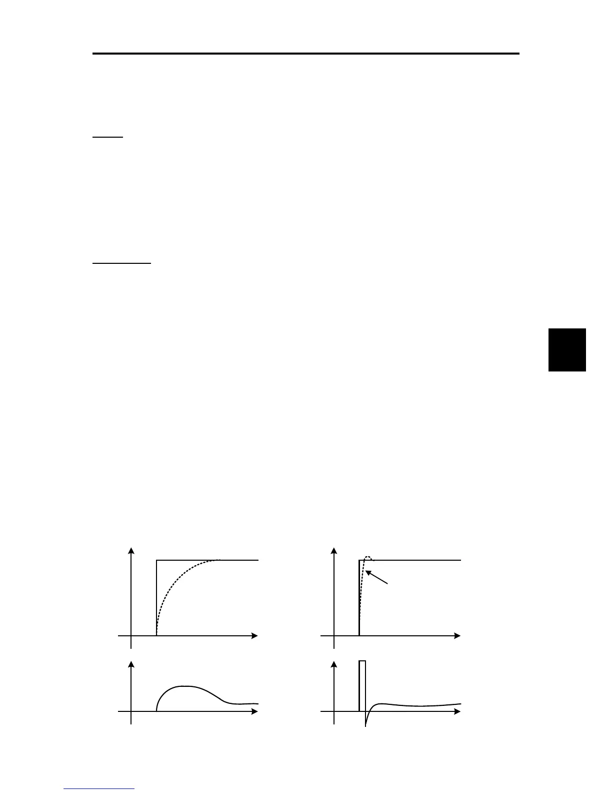
When the moment of inertia is known, this function can be used effectively. Conceptually, as it is shown in the
following figure, the follow-up speed behaviour against the actual speed command is clearly different between feed
forward control valid and invalid. However, to get the maximum effect, it is necessary to adjust this function code
setting and the PI control settings value of the ASR.
The above mentioned effect can be obtained by setting the P gain of ASR higher. However the response of the
system becomes faster in this setting and there is the possibility that it affects negatively due to generation of
vibration.

 Loading...


