2.2 Wiring
2-9
INSTALLATION AND WIRING
Chap 2
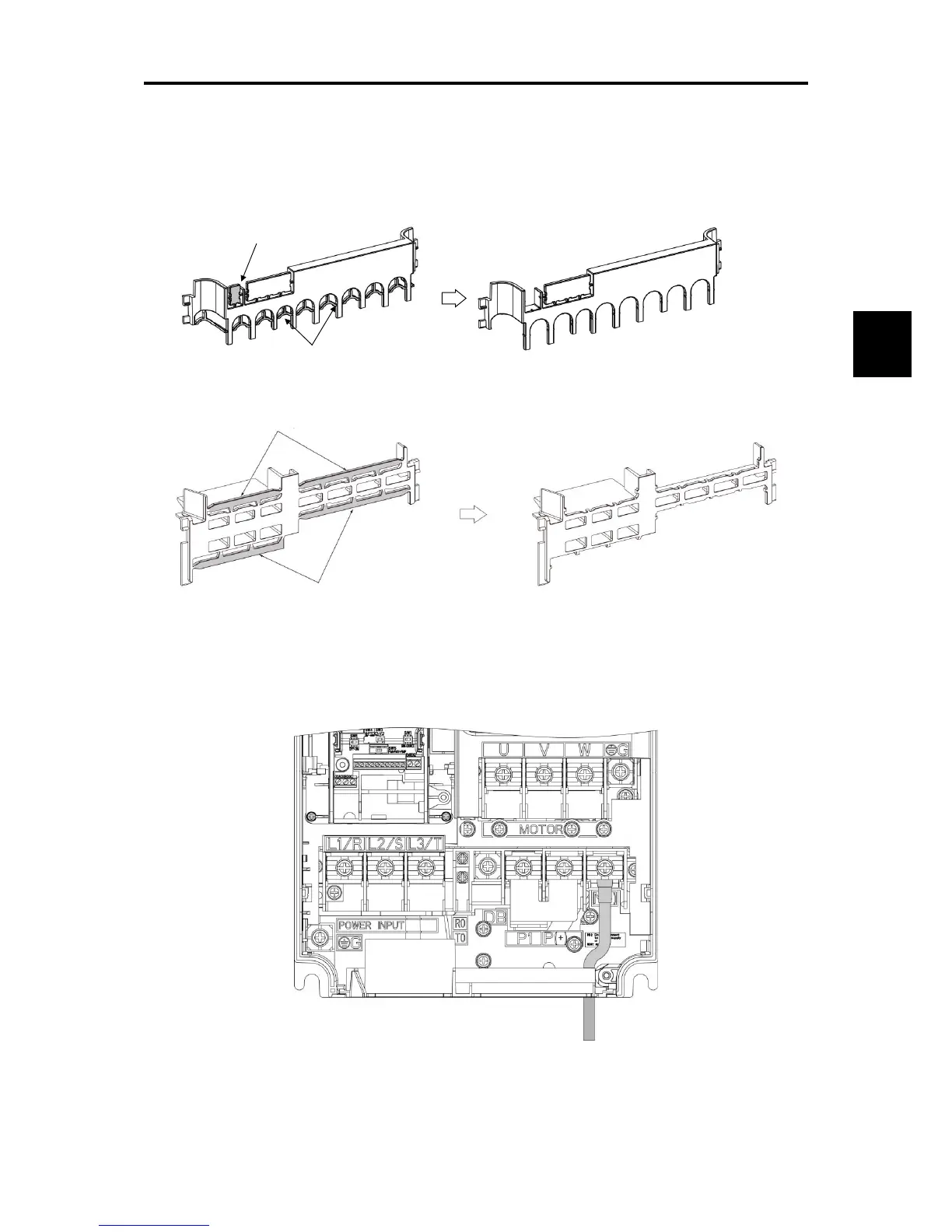
■ Handling the Wiring Guide
For inverter types FRN0001 to 0115E2■-2 and FRN0002 to 0072 E2■-4, the wiring space may become
insufficient when routing the main circuit wires, depending on the wire material used. In these cases, the relevant
cut-off sections (see Figure 2.2-7, Figure 2.2-8) can be removed using a pair of nippers to secure routing space. Be
warned that removing the wiring guide to accommodate the enlarged main circuit wiring will result in
non-conformance to IP20 requirements.
Figure 2.2-7 Wiring Guide (FRN0069E2■-2)
Figure 2.2-8 Wiring Guide (FRN0072E2■-4)
(9) Depending on the inverter capacity, straight routing of the main circuit wires from the main circuit terminal
block may not be possible. In these cases, route the wires as shown in the figure below and securely attach
the front cover.

 Loading...


