Appendix A Trouble-free Use of Inverters (Notes on electrical noise)
Appendix-6
What follows is noise prevention measures for the inverter drive configuration.
(1) Wiring and grounding
As shown in Figure A-7, separate the main circuit wiring from control circuit wiring as far as possible regardless of
being located inside or outside the system control panel containing an inverter. Use shielded wires and twisted
shielded wires that will block out extraneous noises, and minimize the wiring distance. Also avoid bundled wiring of
the main circuit and control circuit or parallel wiring.
Figure A-7 Separate Wiring
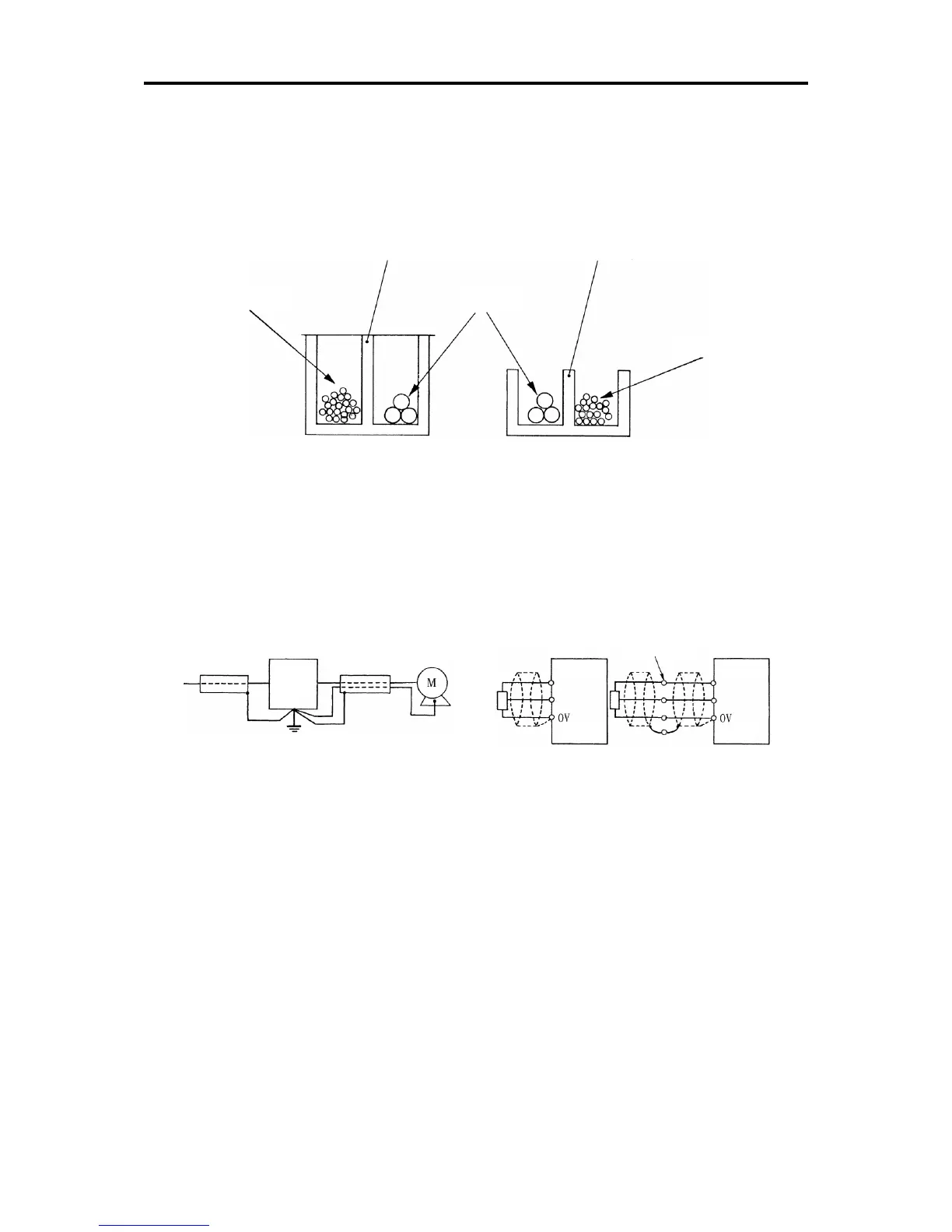
For the main circuit wiring, use a metal conduit pipe and connect its wires to the ground to prevent noise
propagation (refer to Figure A-8).
The shield (braided wire) of a shielded wire should be securely connected to the base (common) side of the signal
line at only one point to avoid the loop formation resulting from a multi-point connection (refer to Figure A-9).
The grounding is effective not only to reduce the risk of electrical shocks due to leakage current, but also to block
noise penetration and radiation. Corresponding to the main circuit voltage, the grounding work should be Class D
(300 VAC or less, grounding resistance: 100Ω or less) and Class C (300 to 600 VAC, grounding resistance: 10Ωor
less). Each ground wire is to be provided with its own ground or separately wired to a grounding point.
Figure A-8 Grounding of Metal Conduit Pipe Figure A-9 Treatment of Braided Wire of Shielded Wire
(2) Control panel
The system control panel containing an inverter is generally made of metal, which can shield noise radiated from
the inverter itself.
When installing other electronic devices such as a programmable logic controller in the same control panel, be
careful with the layout of each device. If necessary, arrange shield plates between the inverter and peripheral
devices.

 Loading...


