2.2 Wiring
2-44
Table 2.2-30 Functional Description of Control Circuit Terminals (continued)
Classification
Terminal
symbol
Terminal name
Functional description
Analog input
[C1] Analog setup
voltage input
(V2 function)
(1) Frequency is set up according to the external analog voltage input command value. SW3
(refer to “2.2.8 Operating slide switches”) must be switched on the printed circuit board.
Normal operation
• DC0 to +10 V/0 to 100(%) (DC0 to +5 V/0 to 100%)
• DC0 to +10 V/-100 to 0 to 100(%) (DC0 to +5 V/-100 to 0 to 100%)
Reverse operation
• DC+10 to 0 V/0 to 100(%) (DC+5 V to 0 V/0 to 100%)
• DC+10 to 0 V/-100 to 0 to 100(%) (DC+5 to 0 V/-100 to 0 to 100%)
(2) The terminal can be assigned to PID command, feedback signal of PID control, auxiliary
frequency setup, ratio setup, torque limit setup, and analog input monitor aside from the
frequency setup by analog input.
(3) Hardware specification
* Input impedance: 22(kΩ)
* Up to DC+15 V can be input. However, input exceeding DC+10 V will be recognized as
DC+10 V.
PTC
thermistor
input
(PTC function)
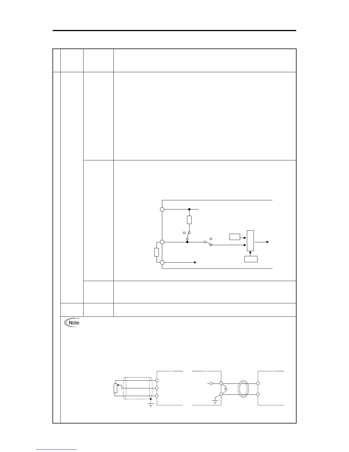
(1) PTC (Positive Temperature Coefficient) thermistor for motor protection can be connected.
SW3 (C1/V2 Switch) and SW4 (PTC /Al Switch) (refer to “2.2.8 Operating slide switches”)
must be switched on the printed circuit board.
Figure 2.2-12 shows the internal circuit when SW3 and SW4 are set for PTC thermistor
input. For details on SW3 and SW4, refer to “2.2.8 Operating slide switches”. When SW3
and SW4 are switched to the PTC side, function codes H26 and H27 also needs to be
changed.
H27
Comparator
【C1】
【13】
DC+10V
0V
【11】
Resistor
1 kΩ
(Operating level)
External
alarm
<Control circuit block>
PTC
thermistor
H26
PTCAi
SW4
SW3
V2
C1
Figure 2.2-12 Internal circuit when SW4 is switched to PTC side
Analog input
monitor
(AI function)
(1) The analog input monitor can be used to monitor the status of peripheral instruments
using communication by inputting the analog signals of various sensors such as
temperature sensors. Data can be converted to physical property values such as
temperature and pressure by using display factors and shown on the keypad display.
[11] Analog input
common
The terminal is the common terminal for analog input signals (terminals [12], [13], [C1]).
The terminal is insulated from terminals [CM], [CMY].
• Use shielded lines and keep the wiring to the minimum as possible (below 20 meters) for control signals
which are susceptible to external noise. Grounding the shielded lines is generally recommended, but if
external induction noise is large, connecting to terminal 11 may reduce the noise. The shielded line
increases the blocking effect. Always ground one end as shown in Figure 2.2-13.
• When inserting a relay contact at analog input signal lines, use the twin contacts relay for small signals.
Also, do not insert a relay to terminal 11.
• When external analog signal generators are connected, the analog signal generator circuit may malfunction
due to the noise created by the inverter. In these cases, connect ferrite core (toroidal shape or equivalent) to
the output terminals of the analog signal generator or connect high frequency capacitors between the
control signal lines, as shown in Figure 2.2-14.
12
13
11
Shielded lines
Variable
resistor 1
to 5 kΩ
<Control circuit block>
12
11
<Control circuit block>
Capacitor
0.022 μF
50 V
Pass through ferrite
core, wind 2 to 3
times as necessary
<Analog signal
generator>
Figure 2.2-13 Connection Diagram for Shielded Lines
Figure 2.2-14 Example of Noise Countermeasures

 Loading...


