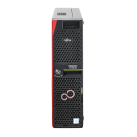
Figure 86: Example: Connecting cables to an HDD backplane
▶
Connect the cables to the HDD backplane:
1 Power cable to the connector “PWR1”
2 Signal cable to the connector “P1”
3 OOB cable to the connector “SMBSYS”
▶
If applicable, place the free connectors in an empty bay
.
▶
Run the cables under the HDD cage.
For the cable plan, see "Appendix B" on page 375
.
Concluding steps
▶
Insert all HDD modules, see "Installing 2.5-inch HDD/SSD modules" on
page 152
.
Ensure that you install the HDD/SSD module in the bay it was located
before the HDD backplane replacement.
▶
Install the HDD fan modules 2.5-inch HDD variant, see "Installing the HDD
fan module (2.5-inch HDD variant)" on page
68
.
Hard disk drive (HDD) / solid state drive (SSD)
TX1320 M5 Upgrade and Maintenance Manual 165

 Loading...