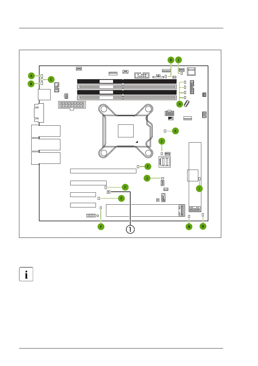
Onboard indicators and controls
CPU
Slot 2
Slot 1
Slot 4
Slot 3
external connectors
LAN 1
Management
LAN
LAN 2
VGA
Shared LAN 1
Micro
SD
FRONT
USB8
PWR4
TYPE A
ROC
FAN2
SYS
P30
PC98
PWR 1
iRMC
S6
TPM
INTRUSION
SATA ODD
Indicate CSS
SATA
0-3
FAN4 SYS
M.2
SSD1
DIMM1A
DIMM1B
DIMM2B
DIMM2A
Battery
HDD
LED
FAN CPU
JP1
JP2
TYPE C
FRONT
SMB
FRONT
USB7
ROC
SERIAL
SYS
Clear
RTC
PWR2
PANEL
Display
Port
JP3
M.2
SSD2
Figure 237: Onboard indicators and Indicate CSS button
1 Indicate CSS button
LEDs A, B and C are visible from outside on the server rear. All other
LEDs are only visible if the server cover has been opened.
If the server has been powered off (power plugs must be disconnected) it is
possible to indicate the faulty component by pressing the indicate CSS button.
The LEDs have the following meaning:
Appendix A
356 Upgrade and Maintenance Manual TX1320 M5

 Loading...