FC2250-UM-251-9370 8-15
8. ELECTRICAL ADJUSTMENTS
8.10 Adjusting the Pen Height
Note: • Before starting the tool height adjustment, make sure that there is no pen or cutter attached to
the pen holder.
• To avoid malfunction of the pen holder, do not touch the pen holder during adjustment.
• Make sure that the pen holder is not in contact with the pen block cover.
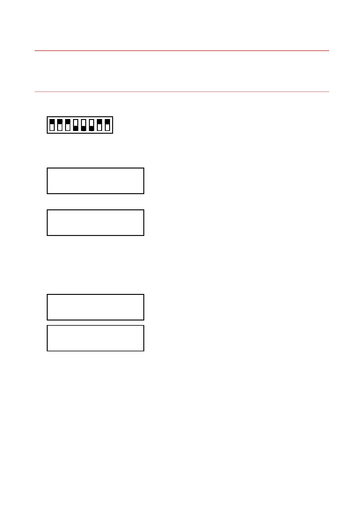
(1) Set the SW1 DIP switch as shown below and then turn on the plotter.
Set Bits 4, 5, and 6 to OFF
12345678
ON
OFF
(2) A menu for electrical adjustment appears on the LCD panel.
(3) Press the [NEXT] key until the LCD displays the following:
TOOL HEIGHT
PRESS ENTER KEY!!
(4) Press the [Enter] key. The LCD screen changes to display the following:
<AUTO ADJ
<DEFAULT POWER>
(5) Press the [F1] (AUTO ADJ) key.
After the message below appears, the plotter automatically adjusts the pen height for the No.1 and No.2
pens.
The beeper sounds twice after adjustment for the No.1 pen has been completed, and then the plotter
automatically adjusts the pen height for the No.2 pen.
No.1 TOOL HEIGHT
C0 A=000 O=300 G=500
No.2 TOOL HEIGHT
C0 A=000 O=300 G=500
(6) When adjustment is completed, turn off the plotter and then return the DIP switch to its default settings
or press the [NEXT] key to proceed to the next adjustment.
(7) Be sure to perform this adjustment whenever the pen block has been replaced.